
User guide
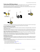

Wiring Diagrams
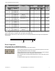
5-pin Euro-Style Hookup
Wiring the 5-pin Euro-style connector depends on the model and power requirements of the device. Connecting dc power to the commu-
nication pins will cause permanent damage.
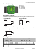
Wire No. Wire Color Description
1 Brown 10 to 30V dc
2 White RS485 / D1 / B / +
3 Blue dc common (GND)
4 Black RS485 / D0 / A / –
5 Gray Comms Gnd
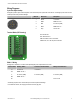
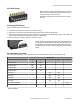
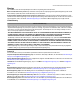
Terminal Block (IP67 Housing)
DO8
DO7
DO6
DO5
DO4
DO3
DO2
DO1
PWR
GND
PWR
GND
DI4
DI3
DI2
DI1
DIx. Discrete IN x.
DOx. Discrete OUT x.
GND. Ground/dc common connection.
PWR. Power, 10 to 30V dc power connection.
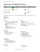
DX80...C Wiring
Wiring power to the DX80...C models varies depending the power requirements of the model.
Terminal Label Gateway, DX85 * 10 to 30V dc Powered Nodes Battery Powered Nodes **
V+ 10 to 30V dc 10 to 30V dc
Tx/+ RS485 / D1 / B / +
V- dc common (GND) dc common (GND) dc common (GND)
Rx/- RS485 / D0 / A / -
B+ 3.6 to 5.5V dc
* Connecting dc power to the communication pins will cause permanent damage.
** For FlexPower devices, do not apply more than 5.5V to the gray wire.
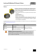
SureCross DX85 Modbus RTU Remote I/O Device
P/N 134325 rev. F www.bannerengineering.com - tel: 763-544-3164 3