
User Manual
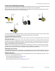
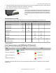

3. Gently unplug the ribbon cable from the board mounted into the bottom housing. For integrated battery models (no ribbon cable) and
Class I, Division 2 certified devices (ribbon cable is glued down), skip this step.
4. Remove the black cover plate from the bottom of the device's cover.
The DIP switches are located behind the rotary dials. After making the neces-
sary changes to the DIP switches, place the black cover plate back into posi-
tion and gently push into place. Plug the ribbon cable in after verifying that
the blocked hole lines up with the missing pin. Mount the cover back onto the
housing.
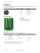
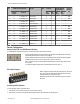
DIP Switch Settings for a DX85
Use the DIP switches 1 through 4 on the board to set the baud rate and parity and DIP switch 5 to set the rotary dial mode.
DIP Switches
1 2 3 4 5
Baud Rate: 19200 OFF* OFF*
Baud Rate: 38400 OFF ON
Baud Rate: 9600 ON OFF
Baud Rate: 19200 ON ON
Parity: None OFF* OFF*
Parity: Even OFF ON
Parity: Odd ON OFF
Parity: None ON ON
Rotary Dial Decimal Mode OFF*
Rotary Dial Hex Mode ON
* Default configuration
Verify Communications on the DX85 Modbus RTU Remote I/O
After powering up, verify the DX85 is communicating properly. LED 1 should be on and green.
Status LED 1 LED 2
Power ON Green ON -
Device error, contact factory Red flashing Red flashing
Modbus communication ac-
tive
- Yellow flashing
Modbus communication error - Red flashing
The Modbus communication LEDs refer to the communication between the DX85 and what it is connected to (host system, Gateway,
Data Radio, etc).
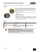
SureCross DX85 Modbus RTU Remote I/O Device
6 www.bannerengineering.com - tel: 763-544-3164 P/N 131599 rev. G