
User guide

Banner Engineering Corp.•Minneapolis,MNU.S.A
www.bannerengineering.com•Tel:763.544.3164
2 P/N 129320 rev. D
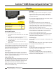
SureCross™ DX80K Wireless Configured FlexPower™ Kit
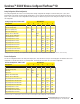
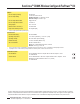
I/O
Point
Terminal Block
Label
DX80 Gateway DXX80 Node Terminal Block
Label
I/O
Point
9 DO1 Discrete OUT 1 Discrete IN 1 (NPN) DI1 1
10 DO2 Discrete OUT 2 Discrete IN 2 (NPN) DI2 2
13 AO1 Analog OUT 1 Analog IN 1+ A1+ 3 QT50U*
14 AO2 Analog OUT 2 Analog IN 2+ A2+ 4
These are the I/O points as displayed on the device LCD. Any I/O points not shown in the chart are not enabled for this kit.
*Thiskitisoptimizedforusewiththespecial,low-powerQT50UUltrasonicsensor.
Configured input/output mapping
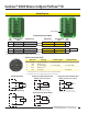
Hookup Diagrams
DI1
DO1
GND
SP3
GND
A1+
A1−
SP1
DI2
DO2
GND
SP4
GND
A2+
A2−
SP2
QT50UPower
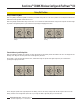
Sourcing Output Wiring
Sinking Input Wiring
A1+
SP1
*
* Do not exceed analog input ratings for analog
inputs. Only connect sensor outputs to analog inputs.
+10 to 30V dc
Ax+
GND
*
dc common
* Do not exceed analog input ratings for analog
inputs. Only connect sensor outputs to analog inputs.
Analog (Sourcing) FlexPower Input
Wiring (switch powered device)
Analog (Sourcing) FlexPower Input
Wiring (externally powered device)
AOx
GND
+10 to 30V dc
Analog (Sourcing) Output Wiring
PWR
GND
AO2
AI2
PWR
GND
DO2
DI2
PWR
GND
AO1
AI1
PWR
GND
DO1
DI1
DOx
GND
DIx
GND
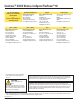
5-pin Euro-style Hookup (RS-485)
Wire Color Gateway 10–30V dc Node FlexPower Node**
1 Brown +10 to 30V dc Input +10 to 30V dc Input
2 White RS485/D1/B/+
3 Blue dc common (GND) dc common (GND) dc common (GND)
4 Black RS485/D0/A/−
5 Gray Comms grnd 3.6to5.5Vdc
* Connectingdcpowertothecommunicationpinswillcausepermanentdamage.
** ForFlexPowerdevices,donotapplymorethan5.5Vdctothegraywire.