
Manual

Banner Engineering Corp.•Minneapolis,MNU.S.A
www.bannerengineering.com•Tel:763.544.3164
2 P/N 134856 rev. B
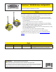
SureCross™ DX80K Wireless Configured Kit
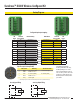
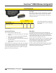
Hookup Diagrams
For additional information,
including installation and setup,
weatherproofing, device menu
maps, troubleshooting, and a list
of accessories, please refer to the
SureCross™ DX80 Wireless I/O
Network product manual, Banner
p/n132607.
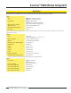
Sourcing Input Wiring
Sourcing Output Wiring
I/O
Point
Terminal
Block Label
DX80 Gateway DX80 Node Terminal
Block Label
I/O
Point
1 DI1 Discrete IN 1 Discrete OUT 1 DO1 9
2 DI2 Discrete IN 2 Discrete OUT 2 DO2 10
3 DI3 Discrete IN 3 Discrete OUT 3 DO3 11
4 DI4 Discrete IN 4 Discrete OUT 4 DO4 12
9 DO1 Discrete OUT 1 Discrete IN 1 DI1 1
9 DO2 Discrete OUT 2 Discrete IN 2 DI2 1
9 DO3 Discrete OUT 3 Discrete IN 3 DI3 1
9 DO4 Discrete OUT 4 Discrete IN 4 DI4 1
9 DO5 Discrete OUT 5 Discrete IN 5 DI5 1
9 DO6 Discrete OUT 6 Discrete IN 6 DI6 1
9 DO7 DiscreteOUT7 DiscreteIN7 DI7 1
9 DO8 Discrete OUT 8 Discrete IN 8 DI8 1
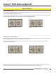
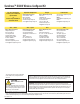
Configured input/output mapping
DIx
PWR
DOx
GND
DO8
DO7
DO6
DO5
DO4
DO3
DO2
DO1
PWR
GND
PWR
GND
DI4
DI3
DI2
DI1
PWR
GND
PWR
GND
DO4
DO3
DO2
DO1
DI8
DI7
DI6
DI5
DI4
DI3
DI2
DI1
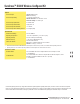
5-pin Euro-style Hookup (RS-485)
Wire Color Gateway 10–30V dc Node
1 Brown +10 to 30V dc Input +10 to 30V dc Input
2 White RS485 / D1 / B / +
3 Blue dc common (GND) dc common (GND)
4 Black RS485 / D0 / A / −
5 Gray Comms grnd
* Connecting dc power to the communication pins will cause permanent damage.