
Instruction Manual
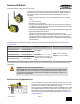
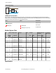

Analog Output Wiring
AOx
GND
dc common
PWR
10-30V dc
sensor
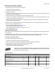
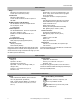
LED Behavior for the Nodes
After powering up and binding the Gateway and its Nodes, verify all devices are communicating properly. A Node will not sample its
inputs until it is communicating with its Gateway. When testing communication between the Gateway and Node, all radios and antennas
should be at least two meters apart or the communications may fail.
LED 1 LED 2 Node Status
(flashing green)
Radio Link Ok
(flashing red) (flashing red)
Device Error
(flashing red, 1 per 3 sec)
No Radio Link
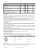
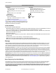
Modbus Register Table
I/O
Modbus Holding Register I/O Type Units I/O Range Holding Register Rep-
resentation
Terminal
Block Labels
Gateway /
DX85
Any Node Min. Max. Min. (Dec.) Max.
(Dec.)
1 1 1 + (Node# × 16) Analog IN 1 mA / V 0.0 20.0 / 10.0 0 65535 AI1
2 2 2 + (Node# × 16) Analog IN 2 mA / V 0.0 20.0 / 10.0 0 65535 AI2
3 3 3 + (Node# × 16) Analog IN 3 mA / V 0.0 20.0 / 10.0 0 65535 AI3
4 4 4 + (Node# × 16) Analog IN 4 mA / V 0.0 20.0 / 10.0 0 65535 AI4
...
7 7 7 + (Node# × 16) Reserved
8 8 8 + (Node# × 16) Device Message
9 9 9 + (Node# × 16) Analog OUT 1 mA / V 0.0 20.0 / 10.0 0 65535 AO1
10 10 10 + (Node# × 16) Analog OUT 2 mA / V 0.0 20.0 / 10.0 0 65535 AO2
11 11 11 + (Node# × 16) Analog OUT 3 mA / V 0.0 20.0 / 10.0 0 65535 AO3
12 12 12 + (Node# × 16) Analog OUT 4 mA / V 0.0 20.0 / 10.0 0 65535 AO4
...
15 15 15 + (Node# × 16) Control Message
16 16 16 + (Node# × 16) Reserved
Specifications
SureCross DX80 Node
P/N 136326 Rev. E www.bannerengineering.com - tel: 763-544-3164 5