
Instruction Manual
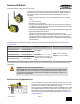
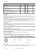

Terminal Label Gateway, DX85 10 to 30V dc Powered Nodes Battery Powered Nodes
V+ 10 to 30V dc 10 to 30V dc
Tx/+ RS485 / D1 / B / +
V- dc common (GND) dc common (GND) dc common (GND)
Rx/- RS485 / D0 / A / -
B+ 3.6 to 5.5V dc
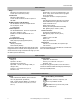
Terminal Blocks
Connecting dc power to the communication pins will cause permanent damage. Do not exceed analog input ratings for analog inputs.
Only connect sensor outputs to analog inputs.
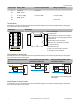
IP67 Housings IP20 Housings
PWR
GND
CM4
CM3
AO4
AO3
AO2
AO1
PWR
GND
CM2
CM1
AI4
AI3
AI2
AI1
AI1
AI2
AI3
AI4
V-
V-
V-
V-
V+
V+
V+
V+
AO1
AO2
AO3
AO4
Tx/+
Rx/-
AIx or Ax. Analog IN x.
AOx. Analog OUT x.
CMx. Serial interface connection. For non-serial in-
terface models, do not make any wiring connections
to these terminals.
GND. Ground/dc common connection.
PWR. Power, 10 to 30V dc power connection.
RX/-. Serial comms line
TX/+. Serial comms line
V+. Power, 10 to 30V dc power connection.
V-. Ground/dc common connection.
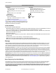
Wiring Diagrams for Analog Inputs
Connecting dc power to the communication pins will cause permanent damage. Do not exceed analog input ratings for analog inputs.
Only connect sensor outputs to analog inputs.
Analog Input Wiring (10 to 30V dc Pow-
er)
Analog Input Wiring (4–20mA, 2-Wire,
Externally Powered Sensors)
Analog Input Wiring (4–20mA, 2-Wire,
Switch Powered Sensors)
AIx
PWR
10-30V dc
GND
− +
sensor
dc common
AIx
GND
dc common
external power
− +
sensor
+
−
AIx
SPx
GND
− +
sensor
dc common
(Only possible in models with switch power
(SPx) outputs)
Wiring Diagrams for Analog Outputs
Connecting dc power to the communication pins will cause permanent damage. Do not exceed analog input ratings for analog inputs.
Only connect sensor outputs to analog inputs.
SureCross DX80 Node
4 www.bannerengineering.com - tel: 763-544-3164 P/N 136326 Rev. E