
User Manual
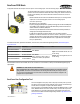
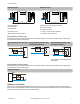

LED 1 LED 2 Node Status
(flashing green)
Radio Link Ok
(flashing red) (flashing red)
Device Error
(flashing red, 1 per 3 sec)
No Radio Link
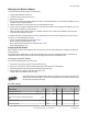
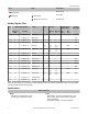
Modbus Register Table
I/O Modbus Holding Register I/O Type Units I/O Range Holding Register
Representation
Terminal
Block Labels
Gateway or
DX85
Any Node Min. Val-
ue
Max. Val-
ue
Min.
(Dec.)
Max.
(Dec.)
1 1 1 + (Node# × 16) Discrete IN 1 - 0 1 0 1 DI1
2 2 2 + (Node# × 16) Discrete IN 2 - 0 1 0 1 DI2
3 3 3 + (Node# × 16) Discrete IN 3 - 0 1 0 1 DI3
4 4 4 + (Node# × 16) Discrete IN 4 - 0 1 0 1 DI4
5 5 5 + (Node# × 16) Analog IN 1 mA
V
0.0
0.0
20.0
10.0
0 65535 AI1
6 6 6 + (Node# × 16) Analog IN 2 mA
V
0.0
0.0
20.0
10.0
0 65535 AI2
7 7 7 + (Node# × 16) Reserved
8 8 8 + (Node# × 16) Device Message
9 9 9 + (Node# × 16) Discrete OUT 1 - 0 1 0 1 DO1
10 10 10 + (Node# × 16) Discrete OUT 2 - 0 1 0 1 DO2
11 11 11 + (Node# × 16) Discrete OUT 3 - 0 1 0 1 DO3
12 12 12 + (Node# × 16) Discrete OUT 4 - 0 1 0 1 DO4
13 13 13 + (Node# × 16) Analog OUT 1 mA
V
0.0
0.0
20.0
10.0
0 65535 AO1
14 14 14 + (Node# × 16) Analog OUT 2 mA
V
0.0
0.0
20.0
10.0
0 65535 AO2
15 15 15 + (Node# × 16) Control Message
16 16 16 + (Node# × 16) Reserved
Some analog I/O models may use milliamps or voltage, depending on the model. Check the models table (on page 1) of your product's
data sheet to determine which model you have.
Specifications
Radio and General
Range
900 MHz: Up to 4.8 kilometers (3 miles)
2.4 GHz: Up to 3.2 kilometers (2 miles)
Power
Requirements: +10 to 30V dc (Outside the USA: +12 to
24V dc, ±10%). (See UL section below for any applica-
ble UL specifications)
Consumption: Less than 1.4 W (60 mA) at 24V dc
SureCross DX80 Node
6 www.bannerengineering.com - tel: 763-544-3164 P/N 131936 Rev. H