
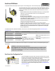
User Manual
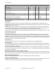
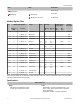

Wire No. Wire Color 10 to 30V dc Powered Nodes Battery Powered Nodes
1
2
3
4
5
1 Brown 10 to 30V dc
2 White
3 Blue dc common (GND) dc common (GND)
4 Black
5 Gray 3.6 to 5.5V dc
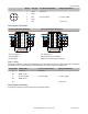
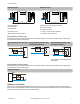
Wiring Diagrams (IP67 Models)
Discrete Input Wiring for PNP Sensors Discrete Input Wiring for NPN Sensors
PWR
GND
AO2
AO1
DO4
DO3
DO2
DO1
PWR
GND
AI2
AI1
DI4
DI3
DI2
DI1
−
+
− +
Load
Load
Load
Load
PWR
GND
AO2
AO1
DO4
DO3
DO2
DO1
PWR
GND
AI2
AI1
DI4
DI3
DI2
DI1
−
+
− +
Load
Load
Load
Load
AIx or Ax. Analog IN x.
AOx. Analog OUT x.
DIx. Discrete IN x.
DOx. Discrete OUT x.
GND. Ground/dc common connection.
PWR. Power, 10 to 30V dc power connection.
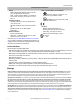
DX80...C Wiring
Wiring power to the DX80...C models varies depending the power requirements of the model. Connecting dc power to the communication
pins (Tx/Rx) will cause permanent damage. For FlexPower devices, do not apply more than 5.5V to the gray wire.
Terminal Label Gateway, DX85 10 to 30V dc Powered Nodes Battery Powered Nodes
V+ 10 to 30V dc 10 to 30V dc
Tx/+ RS485 / D1 / B / +
V- dc common (GND) dc common (GND) dc common (GND)
Rx/- RS485 / D0 / A / -
B+ 3.6 to 5.5V dc
Wiring Diagrams (IP20 Models)
Connecting dc power to the communication pins will cause permanent damage.
SureCross DX80 Node
4 www.bannerengineering.com - tel: 763-544-3164 P/N 131936 Rev. H