
Instruction Manual
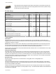

Modbus/User Configuration Tool (UCT) or DIP Switch Configured
In Modbus/UCT Configured mode, the device parameters are changed using the User Configuration Tool (UCT) or a Modbus command.
All DIP switch positions are ignored. In DIP Switch Configured mode, use the DIP switches to configure the parameters listed in the table.
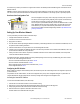
Wiring Your SureCross® Device
Use the following wiring diagrams to first wire the sensors and then apply power to the SureCross devices.
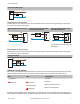
5-pin Euro-Style Hookup
Wiring the 5-pin Euro-style connector depends on the model and power requirements of the device. Connecting dc power to the commu-
nication pins will cause permanent damage.
Wire No. Wire Color Description
1
2
3
4
5
1 Brown 10 to 30V dc
2 White RS485 / D1 / B / +
3 Blue dc common (GND)
4 Black RS485 / D0 / A / –
5 Gray Comms Gnd
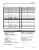
Terminal Block
PWR
GND
AO2
AI2
PWR
GND
DO2
DI2
PWR
GND
AO1
AI1
PWR
GND
DO1
DI1
AIx or Ax. Analog IN x.
AOx. Analog OUT x.
DIx. Discrete IN x.
DOx. Discrete OUT x.
GND. Ground/dc common connection.
PWR. Power, 10 to 30V dc power connection.
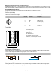
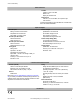
Wiring Diagrams for Discrete Inputs
Connecting dc power to the communication pins will cause permanent damage. For the DX8x...C models, PWR in the wiring diagram
refers to V+ on the wiring board and GND in the wiring diagram refers to V- on the wiring board.
Discrete Input Wiring for PNP Sensors Discrete Input Wiring for NPN Sensors
DIx
PWR
10-30V dc
DIx
GND
dc common
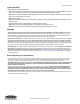
Wiring Diagrams for Discrete Outputs
Connecting dc power to the communication pins will cause permanent damage. For the DX8x...C models, PWR in the wiring diagram
refers to V+ on the wiring board and GND in the wiring diagram refers to V- on the wiring board.
SureCross DX80 Gateway
4 www.bannerengineering.com - tel: 763-544-3164 P/N 131292 Rev. F