
User Manual
* Varies based on the antenna. Please refer to the technical specifications for the specific antenna used in the radio
system.
3
5
1
4
2
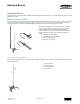
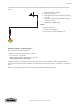
1. RP-SMA connection (–0.5 dB)
2. N-type male connection
3. Surge suppressor (N-type female to N-type male)
(–1.0 dB)
4. N-type male (cable) to N-type female (antenna)
connection (–0.5 dB)
5. Yagi antenna (6 dBd/8.15 dBi)
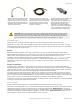
Losses:
–0.5 dB per connection
–1.0 dB per surge suppressor
–3.9 per 100 feet of cable for LMR400 coax
Example Calculation - Complete System
The total losses for the entire system are:
Effective output of the radio system: 25.20 dBm
Free space loss: –105.18 dB
Effective gain of receiving antenna system: 4.20 dBi
Total received power: –75.78 dBm
Compare the total received power to the sensitivity of the radio receiver to determine if the signal will be reliably
received by subtracting the receive sensitivity of the radio from the total received power: –75.78 dBm – (–104 dBm) =
28.22
When the result is greater than 10 dB, the receiver should reliably receive the radio signal.
Antenna Basics
www.bannerengineering.com - tel: 763-544-3164