
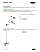
User Manual
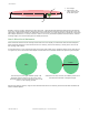
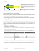
3 dB Yagi
6 dB Yagi
12 dB Yagi
Distance traveled
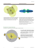
High-Gain Yagis. Because Yagi antennas yield
narrower radiation patterns, accurately aiming a high-
gain Yagi is important when setting up a radio
network. The higher the gain of the antenna, the more
the signal is focused along a specific plane. High-gain
antennas should only be used for line-of-sight
applications.
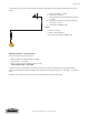
High-gain Yagi antennas are sensitive to mechanical
mounting problems like wind, causing the antennas to
become misaligned.
Path Loss, or Link Loss, Calculations
Path loss, or link loss, calculations determine the exact capabilities of a radio system by calculating the total gain (or loss)
of a radio system.
System Total Gain = Transmitter gain + Free space loss + Receiver gain
The transmitter and receiver gains are typically positive numbers while the free space loss is a larger negative number.
The total gain for any radio system should be negative. Compare this total gain value to the receiver sensitivity of the
Banner SureCross
®
radios listed below.
900 MHz: –104 dBm Sensitivity
2.4 GHz: –100 dBm Sensitivity
Path loss calculations must include all components of a radio system because any item connected to a radio system has a
specific loss associated with it. Common items used within a radio network are cables, connectors, and surge suppressors.
Cabling loss is usually measured per foot while losses for connectors and other items are specific to the component. When
calculating the total gain of a radio system, include losses from all components of the system in your link budget
calculations.
Surge suppressor: 1 dB estimated loss
N-type connectors (per pair): 0.5 dB estimated loss
SMA connector: 0.5 dB estimated loss
LMR400 coax cable: 3.9 dB per 100 ft (0.039 dB per ft) or 0.128 dB per meter (1.28 dB per 10 meters) estimated loss
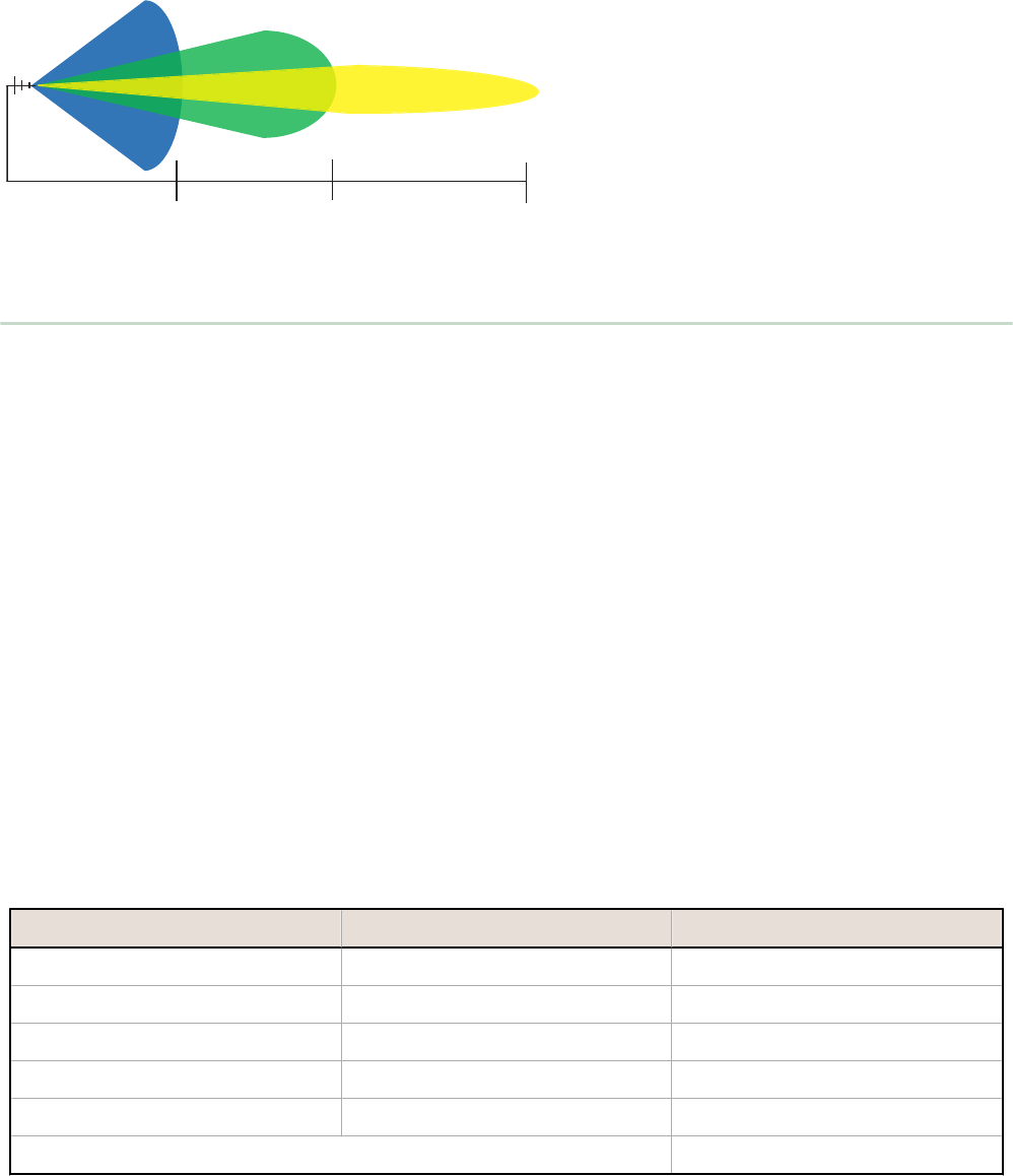
Example Calculation - Transmitter System
To calculate the loss of the transmitter system shown below, include the losses from each connector pair, the surge
suppressor, and the cable.
Device Estimated Gain or Loss
Radio's Power Output DX70 or DX80 radio 21 dBm
Gains (+) or Losses (–) Connector pairs –1.0 dB
Surge suppressor –1.0 dB
Cable (50 ft length) –1.95 dB
Omni antenna* +8.15 dBi
Effective output of radio system 25.2 dBm
* Varies based on the antenna. Please refer to the technical specifications for the specific antenna used in the radio
system.
Antenna Basics
P/N 132113 Rev. H www.bannerengineering.com - tel: 763-544-3164 5