
User Manual
* Default configuration
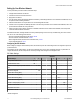
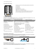
Debounce establishes how to examine a signal’s transitions. The factory default
setting is to activate the input filtering to compensate for unclean state transi-
tions. To turn off the input filtering, set the switch to the ON position.
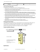
Device switches
Counter switches
Inputs. Counter switches 6 and 7 define the inputs as self-energized, sinking
(NPN), or sourcing (PNP). A self-energized input does not require pull-up or
pull-down devices for proper operation. A magnetic pick-up is a self-energized
input. The input threshold can be adjusted to compensate for low amplitude sig-
nals.
Threshold. The counter has a selectable input threshold of 0.25V or 1.5V. For
sinking (NPN) or sourcing (PNP) inputs, set the threshold to 1.5V.
Wiring Your SureCross® Device
Use the following wiring diagrams to first wire the sensors and then apply power to the SureCross devices.
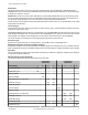
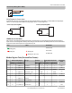
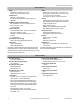
5-pin Euro-Style Wiring (Nodes)
Wiring the 5-pin Euro-style connector depends on the model and power requirements of the device. Connecting dc power to the commu-
nication pins will cause permanent damage. For FlexPower devices, do not apply more than 5.5V to the gray wire.
Wire No. Wire Color 10 to 30V dc Powered Nodes Battery Powered Nodes
1
2
3
4
5
1 Brown 10 to 30V dc
2 White
3 Blue dc common (GND) dc common (GND)
4 Black
5 Gray 3.6 to 5.5V dc
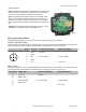
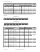
DX80...C Wiring
Wiring power to the DX80...C models varies depending the power requirements of the model. Connecting dc power to the communication
pins (Tx/Rx) will cause permanent damage. For FlexPower devices, do not apply more than 5.5V to the gray wire.
Terminal Label Gateway, DX85 10 to 30V dc Powered Nodes Battery Powered Nodes
V+ 10 to 30V dc 10 to 30V dc
Tx/+ RS485 / D1 / B / +
V- dc common (GND) dc common (GND) dc common (GND)
Rx/- RS485 / D0 / A / -
B+ 3.6 to 5.5V dc
SureCross DX80 FlexPower Counter Node
4 www.bannerengineering.com - tel: 763-544-3164 P/N 136348 Rev. G