
User guide
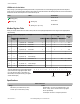

LED Behavior for the Nodes
After powering up and binding the Gateway and its Nodes, verify all devices are communicating properly. A Node will not sample its
inputs until it is communicating with its Gateway. When testing communication between the Gateway and Node, all radios and antennas
should be at least two meters apart or the communications may fail.
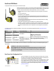
LED 1 LED 2 Node Status
(flashing green)
Radio Link Ok
(flashing red) (flashing red)
Device Error
(flashing red, 1 per 3 sec)
No Radio Link
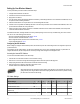
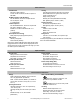
Modbus Register Table
When your wireless network does not include a host system, the four input/eight output Node must be mapped to the eight input/four
output Gateway.
I/O
Point
Modbus Holding Register I/O Type I/O Range Holding Register Representa-
tion
Terminal
Block La-
bels
Gateway/
DX85
Any Node Min. Max. Min. (Dec.) Max. (Dec.)
1 1 1 + (Node# × 16) Discrete IN 1 0 1 0 1 DI1
2 2 2 + (Node# × 16) Discrete IN 2 0 1 0 1 DI2
3 3 3 + (Node# × 16) Discrete IN 3 0 1 0 1 DI3
4 4 4 + (Node# × 16) Discrete IN 4 0 1 0 1 DI4
...
7 7 7 + (Node# × 16) Reserved
8 8 8 + (Node# × 16) Device Message
9 9 9 + (Node# × 16) Discrete OUT 1–8 0 ** 0 255 DO1
...
15 15 15 + (Node# × 16) Control Message
16 16 16 + (Node# × 16) Reserved
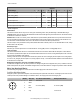
The lower eight bits of the 16-bit unsigned register
represent each of the eight digital outputs. There-
fore, if all outputs are OFF (0) the register con-
tains 0x0000; if all outputs are ON (1) the register
contains 0x00FF (255).
Output 8
Output 2
Output 1
15 14 13 12 11 10 9 8 7 6 5 4 3 2 1 0
Specifications
Radio and General
Range
900 MHz: Up to 4.8 kilometers (3 miles)
2.4 GHz: Up to 3.2 kilometers (2 miles)
Power
Requirements: +10 to 30V dc (Outside the USA: +12 to
24V dc, ±10%). (See UL section below for any applica-
ble UL specifications)
Consumption: Less than 1.4 W (60 mA) at 24V dc
SureCross DX80 Node
P/N 132161 Rev. H www.bannerengineering.com - tel: 763-544-3164 5