
Manual


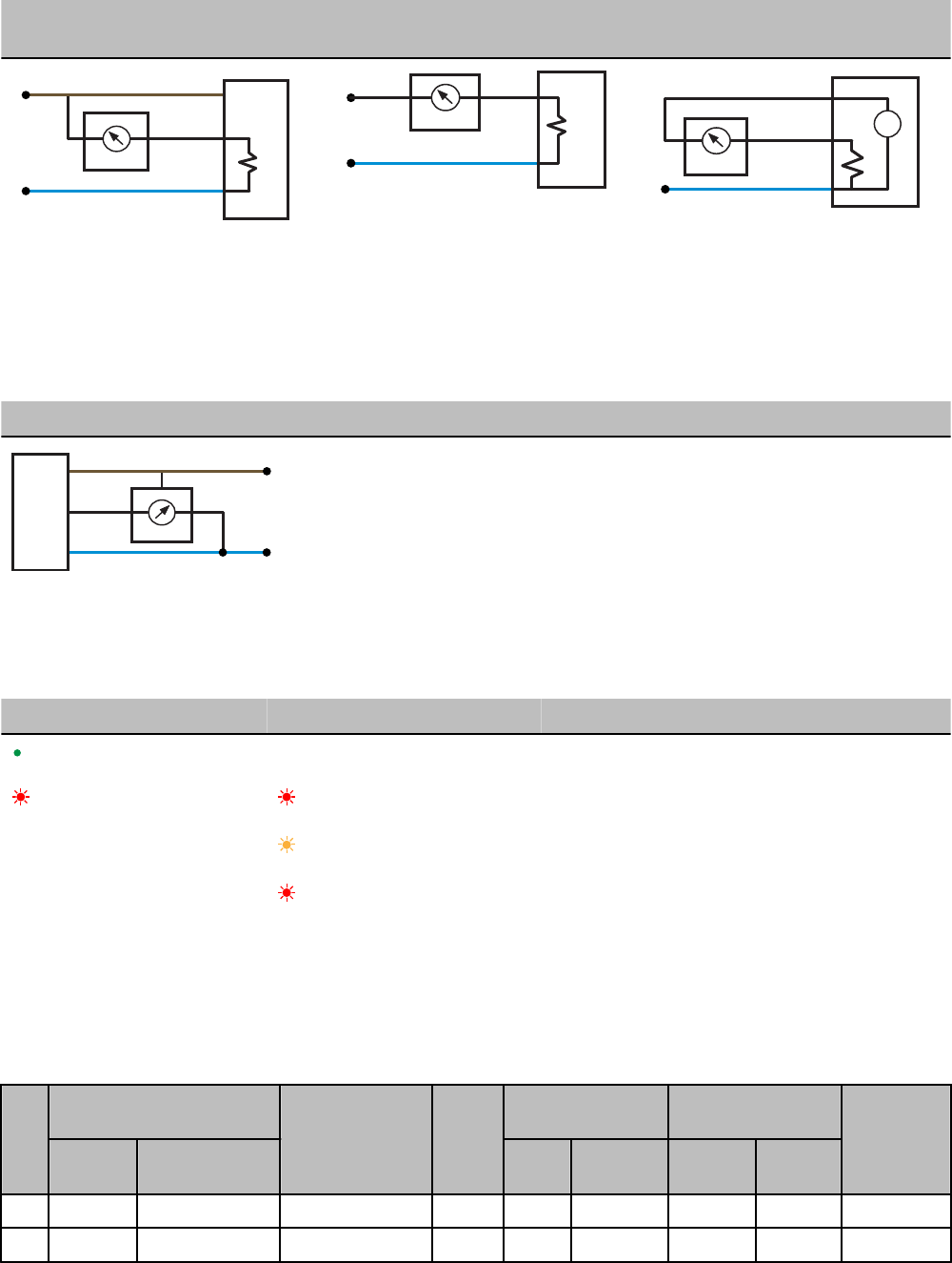
Analog Input Wiring (10 to 30V dc Pow-
er)
Analog Input Wiring (4–20mA, 2-Wire,
Externally Powered Sensors)
Analog Input Wiring (4–20mA, 2-Wire,
Switch Powered Sensors)
AIx
PWR
10-30V dc
GND
− +
sensor
dc common
AIx
GND
dc common
external power
− +
sensor
+
−
AIx
SPx
GND
− +
sensor
dc common
(Only possible in models with switch power
(SPx) outputs)
Wiring Diagrams for Analog Outputs
Connecting dc power to the communication pins will cause permanent damage. Do not exceed analog input ratings for analog inputs.
Only connect sensor outputs to analog inputs.
Analog Output Wiring
AOx
GND
dc common
PWR
10-30V dc
sensor
LED Behavior for the Gateways
After powering up and binding the Gateway and its Nodes, verify all devices are communicating properly. When testing communication
between the Gateway and Node, all radios and antennas should be at least two meters apart or the communications may fail.
LED 1 LED 2 Gateway Status
(solid green)
Power ON
(flashing red) (flashing red)
Device Error
(flashing yellow)
Modbus Communication Active
(flashing red)
Modbus Communication Error
For Gateway and Ethernet Bridge systems, active Modbus communication refers to the communication between the Gateway and the
Ethernet Bridge. For GatewayPro systems, the Modbus communication LEDs refer to the communication internal to the GatewayPro. For
Gateway only systems, the Modbus communication LEDs refer to the communication between the Gateway and its host system (if appli-
cable).
Modbus Register Table
I/O
Modbus Holding Register I/O Type Units I/O Range Holding Register Rep-
resentation
Terminal
Block Labels
Gateway /
DX85
Any Node Min. Max. Min. (Dec.) Max.
(Dec.)
1 1 1 + (Node# × 16) Analog IN 1 mA / V 0.0 20.0 / 10.0 0 65535 AI1
2 2 2 + (Node# × 16) Analog IN 2 mA / V 0.0 20.0 / 10.0 0 65535 AI2
SureCross DX80 Gateway
P/N 136325 Rev. F www.bannerengineering.com - tel: 763-544-3164 5