
Instruction Manual
Banner Engineering Corp.•Minneapolis,MNU.S.A
www.bannerengineering.com•Tel:763.544.3164
2 P/N 129318 rev. D
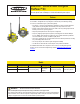
SureCross™ DX80K Wireless Configured FlexPower™ Kit
For additional information, including installation and setup, weatherproofing, device menu maps, troubleshooting, and a list of accessories,
please refer to the SureCross™DX80WirelessI/ONetworkproductmanual,Bannerpartnumber132607.
I/O
Point
Terminal Block
Label
DX80 Gateway DX80 Node Terminal Block
Label
I/O
Point
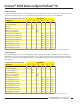
9 DO1 Discrete OUT 1 Discrete IN 1 DI1 1 MINI-BEAM®*
10 DO2 Discrete OUT 2 Discrete IN 2 DI2 2
Configured input/output mapping
These are the I/O points as displayed on the device LCD. Any I/O points not shown in the chart are not enabled for this kit.
* Special low-power MINI-BEAM
®
required when powered by the Node
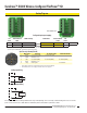
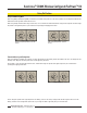
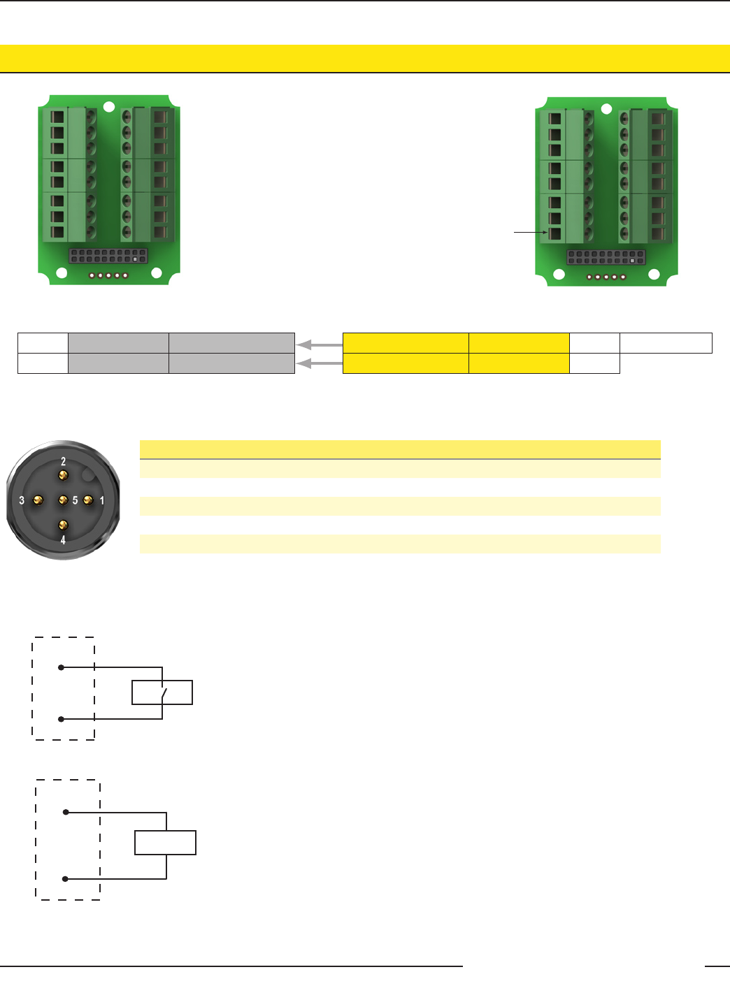
Hookup Diagrams
DI1
DO1
GND
SP3
GND
A1+
A1−
SP1
DI2
DO2
GND
SP4
GND
A2+
A2−
SP2
MINI-BEAM
®
Power
Sinking Input Wiring
Sourcing Output Wiring
PWR
GND
DO4
DI4
PWR
GND
DO2
DI2
PWR
GND
DO3
DI3
PWR
GND
DO1
DI1
DOx
GND
DIx
GND
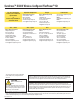
5-pin Euro-style Hookup (RS-485)
Wire Color Gateway 10–30V dc Node FlexPower Node**
1 Brown +10 to 30V dc Input +10 to 30V dc Input
2 White RS485/D1/B/+
3 Blue dc common (GND) dc common (GND) dc common (GND)
4 Black RS485/D0/A/−
5 Gray Comms grnd 3.6to5.5Vdc
* Connecting dc power to the communication pins will cause permanent damage.
** For FlexPowerdevices,donotapplymorethan5.5Vdctothegraywire.