
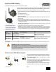
Instruction Manual

I/O
Point
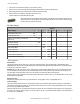
Modbus Holding Register I/O Type I/O Range Holding Register Representa-
tion
Terminal
Block La-
bels
Gateway/
DX85
Any Node Min. Max. Min. (Dec.) Max. (Dec.)
7 7 7 + (Node# × 16) Reserved
8 8 8 + (Node# × 16) Device Message
9 9 9 + (Node# × 16) Discrete OUT 1–8 0 ** 0 255 DO1
...
15 15 15 + (Node# × 16) Control Message
16 16 16 + (Node# × 16) Reserved
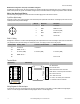
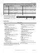
The lower eight bits of the 16-bit unsigned register
represent each of the eight digital outputs. There-
fore, if all outputs are OFF (0) the register con-
tains 0x0000; if all outputs are ON (1) the register
contains 0x00FF (255).
Output 8
Output 2
Output 1
15 14 13 12 11 10 9 8 7 6 5 4 3 2 1 0
Specifications
Radio and General
Range
900 MHz: Up to 4.8 kilometers (3 miles)
2.4 GHz: Up to 3.2 kilometers (2 miles)
Transmit Power
900 MHz: 21 dBm (150 mW) conducted
2.4 GHz: 18 dBm (65 mW) conducted, less than or
equal to 20 dBm (100 mW) EIRP
900 MHz Compliance (150 mW Radios)
FCC ID TGUDX80 - This device complies with FCC
Part 15, Subpart C, 15.247
IC: 7044A-DX8009
2.4 GHz Compliance
FCC ID UE300DX80-2400 - This device complies with
FCC Part 15, Subpart C, 15.247
ETSI/EN: In accordance with EN 300 328: V1.7.1
(2006-05)
IC: 7044A-DX8024
Spread Spectrum Technology
FHSS (Frequency Hopping Spread Spectrum)
Link Timeout
Gateway: Configurable
Node: Defined by Gateway
Radio range is with the 2 dB antenna that ships with the product.
High-gain antennas are available, but the range depends on the
environment and line of sight. To determine the range of your wire-
less network, perform a Site Survey.
Power
Requirements: +10 to 30V dc (Outside the USA: +12 to
24V dc, ±10%). (See UL section below for any applica-
ble UL specifications)
Consumption: Less than 1.4 W (60 mA) at 24V dc
Housing
Polycarbonate housing and rotary dial cover; polyester
labels; EDPM rubber cover gasket; nitrile rubber, non-
sulphur cured button covers
Weight: 0.26 kg (0.57 lbs)
Mounting: #10 or M5 (SS M5 hardware included)
Max. Tightening Torque: 0.56 N·m (5 lbf·in)
Antenna Connection
Ext. Reverse Polarity SMA, 50 Ohms
Max Tightening Torque: 0.45 N·m (4 lbf·in)
Interface
Indicators: Two bi-color LEDs
Buttons: Two
Display: Six character LCD
Wiring Access
Four PG-7, One 1/2-inch NPT, One 5-pin Euro-style
male connector
For European applications, power the DX80 from a Limited Power
Source as defined in EN 60950-1.
SureCross DX80 Gateway
6 www.bannerengineering.com - tel: 763-544-3164 P/N 132158 Rev. H