
Instruction Manual

Banner Engineering Corp.•Minneapolis,MNU.S.A
www.bannerengineering.com•Tel:763.544.3164
2 P/N 135607 rev. B
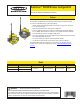
SureCross™ DX80K Wireless Configured Kit
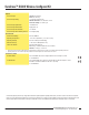
Hookup Diagrams
For additional information, including
installation and setup, weatherproofing,
device menu maps, troubleshooting, and
a list of accessories, please refer to the
SureCross™ DX80 Wireless I/O Network
product manual, Banner p/n 132607.
I/O
Point
Terminal
Block Label
DX80 Gateway DX80 Node Terminal
Block Label
I/O
Point
1 DI1 Discrete IN 1 Discrete OUT 1 DO1 9 Node 1
2 DI2 Discrete IN 2 Discrete OUT 1 DO1 9 Node 2
3 DI3 Discrete IN 3 Discrete OUT 1 DO1 9
Node 3
4 DI4 Discrete IN 4 Discrete OUT 1 DO1 9 Node 4
5 DI5 Discrete IN 5 Discrete OUT 1 DO1 9 Node 5
6 DI6 Discrete IN 6 Discrete OUT 1 DO1 9 Node 6
9 DO1 Discrete OUT 1 Discrete IN 1 DI1 1 Node 1
10 DO2 Discrete OUT 2 Discrete IN 1 DI1 1 Node 2
11 DO3 Discrete OUT 3 Discrete IN 1 DI1 1 Node 3
12 DO4 Discrete OUT 4 Discrete IN 1 DI1 1 Node 4
13 DO5 Discrete OUT 5 Discrete IN 1 DI1 1 Node 5
14 DO6 Discrete OUT 6 Discrete IN 1 DI1 1 Node 6
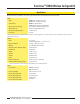
These are the I/O points as displayed on the device LCD. Any I/O points not shown in the chart are not enabled for this kit.
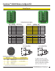
Configured input/output mapping
Sourcing Input Wiring
Sourcing Output Wiring
PWR
GND
DO6
DO5
DO4
DO3
DO2
DO1
PWR
GND
DI6
DI5
DI4
DI3
DI2
DI1
PWR
GND
DO4
DI4
PWR
GND
DO2
DI2
PWR
GND
DO3
DI3
PWR
GND
DO1
DI1
DIx
PWR
DOx
GND
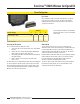
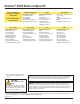
5-pin Euro-style Hookup (RS-485)
Wire Color Gateway 10–30V dc Node
1 Brown +10 to 30V dc Input +10 to 30V dc Input
2 White RS485 / D1 / B / +
3 Blue dc common (GND) dc common (GND)
4 Black RS485 / D0 / A / −
5 Gray Comms grnd
* Connecting dc power to the communication pins will cause permanent damage.