
Owner's manual
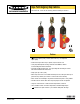
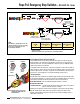

Rope Pull Emergency Stop Switches – RP-LS42F-75L.. Series
6 P/N 67709 rev. A
Banner Engineering Corp. • Minneapolis, MN U.S.A.
www.bannerengineering.com • Tel: 763.544.3164
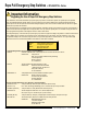
Electrical Installation
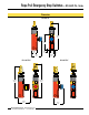
Access to Wiring Chamber
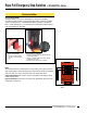
The wiring chamber is accessed via the hinged door. Simply insert a flat-blade
screwdriver, as shown in Figure 5, and pry gently down to open. Select the best wiring
entrance and thread in the ½" x 14 NPSM conduit adapter (supplied), or the optional
M20 x 1.5 cable gland (page 11). The switch knockout will break loose with the final turn
of the conduit adapter or cable gland.
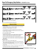
Figure 5. Access to wiring chamber – use a small flat-blade screwdriver
To connect wires to terminals:
1. Insert the screwdriver blade into the slot below the
desired wiring terminal.
2. Twist the screwdriver blade in the slot to open the
terminal jaws; insert wire.
3. Hold wire in place and remove screwdriver.
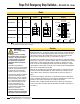
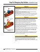
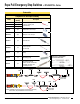
Wiring
These switch models have redundant pairs of safety contacts, so they may be wired for
either single-channel or dual-channel output to a safety module or E-stop circuit. Monitor
contacts, in either case, may be wired as desired to an external alarm device.
Single-Channel Output: Wire contacts 21/22 or 41/42 together to the input of a safety
module or E-stop circuit.
Dual-Channel Output: Wire contacts 21/22 and 41/42 independently to the two safety
module inputs (see Figure 6).
Figure 6. Wire the two switch contacts in
series
41 42 33 34
13 14 21 22
Dual-Channel Safety Device
CH 1CH 2
To open wiring chamber:
1. Insert the screwdriver blade
into slot in cover to pry cover
open.