
Owner's manual

Rope Pull Emergency Stop Switches – RP-LS42F-75L.. Series
4 P/N 67709 rev. A
Banner Engineering Corp. • Minneapolis, MN U.S.A.
www.bannerengineering.com • Tel: 763.544.3164
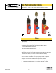
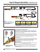
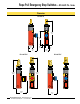
Figure 1. Run, rope pulled, and rope break switch positions
Run Position: Proper Rope Tension
Rope Pulled: Contacts S21/22 and 41/42 Open
Rope Break or Slack: Contacts S21/22 and 41/42 Open
Mechanical Installation
Installation Guidelines
• The wire rope should be easily accessible and visible along its entire length. Markers
or flags may be fixed on the rope to increase its visibility.
• Mounting points, including support points, must be rigid.
• The rope should be free of friction at all supports. Pulleys are recommended.
• Use only pulleys (not eye bolts) when routing the rope around a corner, or whenever
direction is changed, even slightly.
• Never run rope through conduit or other tubing.
• Never attach weights to the rope.
• Temperature affects rope tension. The rope expands (lengthens) when temperature
increases, and contracts (shrinks) when temperature decreases. Significant
temperature variations require frequent checks of the tension adjustment.
• Do not exceed the maximum total rope length, as specified in Figure 3. Banner offers
models for greater spans; contact the factory or visit www.bannerengineering.com for
model selection.
Installation Procedure
1. Mount the switch securely on a solid, stationary surface.
2. Fasten an eye bolt at the opposite end of the rope span, up to 75 m (245') from the
switch. The anchor for the eye bolt also must be solid and stationary, to withstand the
constant tension and possible pull of the rope.
3. Assemble the rope, as shown in Figure 3. Keep the rope’s PVC cover intact along its
complete length.
4. Use pulleys (recommended) or eye bolts at each support point. A pulley must be used
when routing the rope around a corner, regardless of the angle.
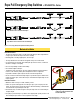
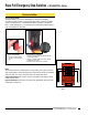
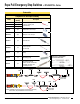
Figure 2. Tightening the rope into the internal
turnbuckle (models RP-LS42F-75LE
and RP-LS42F-75LF)