
Owner's manual
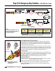

Rope Pull Emergency Stop Switches – RP-LS42F-75L.. Series
P/N 67709 rev. A 3
Banner Engineering Corp. • Minneapolis, MN U.S.A.
www.bannerengineering.com • Tel: 763.544.3164
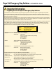
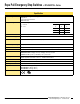
Models
Model
†
E-Stop
Built-in
Turnbuckle
Run
Position
Cable Pulled/
Cable Break
Switching
Diagram
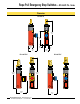
RP-LS42F-75L No No
RP-LS42F-75LE Yes Yes
RP-LS42F-75LF No Yes
21 22
13 14
41 42
33 34
21 22
13 14
41 42
33 34
21 22
13 14
41 42
33 34
21 22
13 14
41 42
33 34
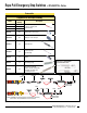
13-14
21-22
Break (180N)
Tension
Set Point
240N
Latch
Pull (300N)
-5 (0.20)
+5 (0.20)
-3.8 (0.15)
-3 (0.12)
+3 (0.12)
mm (in)
+3.8 (0.15)
33-34
41-42
Latch
Overview
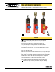
Models RP-LS42F-75L.. are rope pull emergency stop switches in compact, limit switch-
style housings made of high-impact thermoplast. When used with steel wire rope, they
can provide emergency stop actuation along conveyors and similar machinery. Red
PVC-covered 3 mm diameter wire rope is recommended (see page 10).
The switches have redundant contacts; terminals 21/22 and 41/42 are positive opening
when there is a cable-pull or cable-brake situation. When used separately, these contacts
provide inputs to a dual-channel safety module (see Figure 6). Terminals 21/22 and
41/42 can also be used individually to provide single-channel switching or as a single-
channel input to a safety module. Terminals 13/14 and 33/34 are for monitoring purposes
only (closed in a cable-brake/-pull situation).
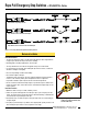
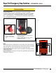
When the rope is properly tensioned (240N), the red arrows are centered on the hash
mark on the tension indicator window, the contacts at terminals 21/22 and 41/42 are
closed, and the contacts at terminals 13/14 and 33/34 are opened (see Figures 1, 2
and 4).
These rope pull emergency stop switches are not generally considered safeguarding
devices, in that they do not prevent or reduce exposure of individuals to a hazard. They
provide the same function as other types of emergency stop switches.
All models feature “latching” operation. When the rope is pulled, the switch contacts
21/22 and 41/42 open and remain open until the built-in reset button is manually reset
(see Figure 1).
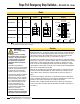
WARNING ...
Not a Safeguarding
Device
An Emergency Stop Device, including,
but not limited to buttons, rope pulls and
cable pulls, is not generally considered
a safeguard; and does not alone fulfill
U.S. or International requirements for
safeguarding hazards associated with
machinery.
The definition of safeguarding is the
"protective measure using safeguards [guards
or protective devices] to protect persons from
the hazards which cannot reasonably be
eliminated..." (ISO12100-1, 3.29 and 3.30).
A safeguard limits or eliminates an individual's
exposure to a hazard (examples include
interlocking devices, safety mats, safety light
screens). An emergency stop is considered
to be a complementary protective measure,
which is neither an inherently safe design
measure, nor safeguarding, but may
be required as part of the safety related
control system and risk reduction strategy
(ISO12100-2, 4.5.1 and 4.5.2).
The user must refer to the relevant
standard(s) to determine the safeguarding
requirements for their particular situation.
NOTE: This symbol for a positive-opening safety contact (IEC 60947-5-1) is used in the switching diagram to identify the point in actuator travel where
the normally-closed safety contact is fully open.
Contacts:
Open Closed Transition