
User guide


Installation
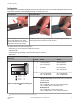
Multiple sensor pairs located farther than the sensor's effective maximum range (approximately 2 m or 6.5 ft) from one another are unlike-
ly to cause crosstalk problems. However, when multiple sensor pairs are mounted in a confined area, take care to avoid crosstalk be-
tween them. To avoid crosstalk:
• Alternate the relative position of adjacent emitter/receiver pairs.
• Alternate the Frequency configuration of adjacent pairs.
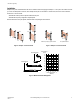
Mount emitter and receiver pairs parallel, with both cable ends pointing the same direction.
MODE
Emitter
Receiver
Receiver
Emitter
MODE
MODE
Emitter
Receiver
MODE
Receiver
Emitter
Figure 1. Example—Correct Positions
Receiver
Emitter
MODE
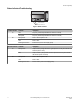
Cable ends pointing in opposite directions
MODE
Emitter
Receiver
Non-parallel orientation
Figure 2. Example—Incorrect Positions
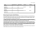
0
0
0.2
0.4
0.6
0.8
1.0
1.2
1.4
1.6
1.8
2.0
25020015010050
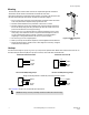
Sensor Separation – Y
(Meters)
Horizontal Misalignment
Vertical Misalignment
Maximum Off-axis Distance – X
(Millimeters)
X
Y
X
Y
Figure 3. Maximum Off-Axis Misalignment
PVA Pick-to-Light Array
P/N 52088_web
Rev. E
www.bannerengineering.com - tel: 763-544-3164 3