
Manual

•
•
•
•
•
MICRO-AMP
®
System
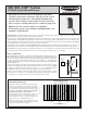
SP100AF Adjustable-field Sensor
Optical/Electrical design ensures an adjustable range limit,
regardless of the surface reflectivity of the objects to be sensed
Powerful infrared light source and modulated amplification
provide reliable sensing of objects with low surface reflectivity
Sensor response to background objects is completely suppressed
Miniature size fits easily into tight areas of machines
Works with a special version of Banner's MICRO-AMP
®
series
amplifiers, model MA3AF
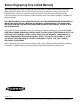
Deviation is defined as the difference in the switch point
between a 90% reflectance test card and a 10% reflec-
tance test card. The switch point is measured by using the
test cards as they approach the front of the sensor. Use
the chart at the right to determine the maximum
switch point deviation at various distances.
Example: When the range is adjusted for .12 inches off
a 90% reflectance test card, the minimum range for a
10% reflectance test card is .11 inches. Distance (.12)
minus Deviation (.01) = Minimum range (.11)
Maximum operating range of 10% reflectance test card
is 0.1 to.20 inches. Maximum operating range of 90%
reflectance test card is 0.1 to .40 inches.
SP100AF Deviation Curve
Printed in USA P/N 34002UHY%
Model SP100AF is an adjustable-field convergent mode sensor that detects objects directly by reflection of light from the object's surface. Objects
in the background are ignored, regardless of their surface reflectivity.
This sensing response feature makes the SP100AF an ideal choice for detecting a part or a surface that is only a small fraction of an inch in front
of another surface. The SP100AF is highly reliable for semiconductor wafer sensing. Wafers of all reflectivities are sensed without system
sensitivity adjustment. Other applications include cut-to-length control, double-thickness detection, and precision edgeguiding. The SP100AF
is an excellent choice for precise position control (e.g. as a robotic end effector).
The SP100AF works in conjunction with Banner MICRO-AMP modulated amplifier model MA3AF. The model MA3AF is powered by +10
to 30V dc and uses a model RS8 socket. This amplifier has a 4-turn RANGE potentiometer for precise adjustment of the sensing distance.
The SP100AF has enough optical energy to reliably sense material of very low reflectivity such as nitride-coated semiconductor wafers. The
typical peak signal point is 0.13 inch from the sensor face. The recommended operating range is .12 to .20 inches.
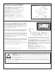
Theory of Operation
R
E1
E2
Crossover point
Mininmum sensing distance
Maximum sensing distance
Sensing area
Sensor face
(Side view
of sensor)
Object
approaching
from front
SP100AF Concept
The SP100AF uses two LEDs that operate with the modulated amplifier in a differential mode. The
LEDs are mechanically convergent with the receiver photoelement at two different distances from
the sensor face. If photoelement (R) receives light that is emitted from the inner photoelement (E1),
a positive-going pulse is produced which turns the output of the amplifier "on". When light from
outer photoelement (E2) is received by photoelement (R), a negative-going pulse is produced which
turns the amplifier "off".
A target is sensed whenever the amount of light from E1 reaching receiver R is equal to or greater
than the amount of light from E2. The output of the amplifier is cut off as soon as the amount of light
from E2 becomes greater than at E1. The location of this crossover point is adjustable via the 4-
turn
RANGE potentiometer and remains the same regardless of the target's reflectivity.
Reflections even from highly-polished mirror-like surfaces are ignored if the reflections originate
from beyond the crossover point. Also, modulated LED design offers very high excess gain at the
convergent point. As a result, even objects of very low reflectivity may be sensed.
.01 in.
.02 in.
.03 in.
.04 in.
.05 in.
.10 in.
(2,5 mm)
.15 in.
(3,8 mm)
.20 in.
(5,1) mm
.25 in.
(6,4 mm)
.06 in.
DISTANCE
(Referenced to 90% reflectance test card)
D
E
V
I
A
T
I
O
N
SP100AF DEVIATION CURVE
recommended operating range
.12 - .20 inches
0,25 mm
0,50 mm
0,75 mm
1,00 mm
1,25 mm
1,50 mm