
Instruction Manual

SP1000V
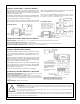
Hookup to MB Series Ampliers
Banner remote sensors will connect to any MB Series amplier. The
model MRB chassis (shown) has octal sockets for the amplier and a
BR-2 relay (supplied) and provides power for the sensors and ampli-
er. Up to four sensor pairs may be connected to one amplier for
light-operated OR or dark operated AND operation. In multiple-sensor
hookups, receivers are wired in parallel and emitters are connected in
series (see example for CM Series modules, next page).
Several MB Series ampliers are available. Each provides a different
output logic function. Chassis models with additional octal sockets
are also available. Other types of output devices, including solid state
relays, may be ordered (see Banner catalog).
Specications, MB Series Ampliers
POWER SUPPLY REQUIREMENT: 12-18V dc at less than 100mA,
exclusive of load.
OUTPUT CONFIGURATION: open collector NPN transistor; maximum
on-state current 250mA, maximum off-state leakage current 100 micro-
RESPONSE SPEED: 1 millisecond ON and OFF.
MAXIMUM SENSOR LEAD LENGTH: 100 feet (30m) maximum;
use separate shielded cables for emitter and receiver.
OPERATING TEMPERATURE RANGE: 0 to +50°C (+32 to +122° F).
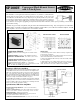
BEAM PATTERN
EXCESS GAIN CURVE
Convergent Mode Remote Sensor
with 3.8-inch focus
P/N 03391C4B
Printed in USA
RANGE: produces 0.1" dia. sensing spot 3.8" from the sensor
face
RESPONSE SPEED: a function of the amplier (see below)
OPERATING TEMPERATURE: -40 to +80° C (-40 to +176°
F)
EMITTER CHARACTERISTICS: infrared LED, 880nm
CONSTRUCTION: totally encapsulated, glass lenses.
Anodized aluminum housing; NEMA 1, 3, 4, 12, and 13.
CABLE: sensors are supplied with 6' of 4-conductor PVC-covered
cable. 30' cables are available by special order.
Specications, SP1000V
1) Avoid running remote sensor cables in wireways together with
power-carrying conductors.
Wiring rules:
2) Avoid running remote sensor cables through areas of known ex-
treme electrical interference (electrical "noise").
3) Always use shielded cables and only connect the shield ("drain")
wire at the amplier.
4) When splicing, never combine emitter and receiver wires into a
common cable. (The result will be electrical "crosstalk" within the
cable, which causes a "lock-on" condition of the amplier.)
The SP1000V is a convergent mode sensor that produces a very small 0.1" (2,5mm) diameter
sensing image at a point exactly 3.8" (96mm) in front of its glass lenses. As the excess gain
curve illustrates, the SP1000V has a very sharp drop-off of gain beyond the focus point. This
feature makes it an ideal choice for detecting a small part which is only a fraction of an inch in
front of another surface, such as small parts on a conveyor (viewed from above). The SP1000V
is also ideal for cut-to-length or edgeguiding of transparent materials, ll level detection, and for precise positioning control in lieu of
opposed mode sensing.
SP1000V sensors are totally encapsulated, with glass lenses and anodized aluminum housings. They are designed for use with Banner
MICRO-AMP
®
system MA3-4 and MA3-4P modulated ampliers, MAXI-AMP™ system CM Series modulated ampliers, and MB
Series ampliers. Six feet of 4-conductor PVC-covered cable is standard.