
User guide

•
•
•
APC Seriplex
®
networks offer unprecedented simplicity,
economy, and noise-immunity in industrial control systems
APC Seriplex networks are modular I/O systems capable of
controlling up to 510 digital I/O points on a single network
Using built-in Seriplex circuitry and assignable address codes,
OMNI-BEAM PHOTOBUS™ power blocks establish logical
relationships between the outputs of OMNI-BEAM™ sensors
and other Seriplex-compatible devices on the network
OPBX2 Series PHOTOBUS™ power blocks may be used with
all OMNI-BEAM™ Standard and E Series sensor heads
Seriplex is a registered trademark of APC. PHOTOBUS and OMNI-
BEAM are trademarks of Banner Engineering Corp.
OMNI-BEAM PHOTOBUS™ OPBX2 Series Power Blocks are APC Seri-
plex
®
compatible and may be used on Seriplex networks with any OMNI-BEAM
Standard (OSB__) or E Series (OSE_) Sensor Head.
In use, OPBX2 Series Power Block-equipped OMNI-BEAM™ sensors, the
devices to be controlled, a dc power supply, and a clock module all connect to
a common network. One wire of the network supplies dc voltage of +9 to 12
volts, one wire is common (ground), another carries data, and another carries
a synchronous, continuously-recycling clock signal. Each power block has a
built-in EEPROM that is programmed, by the user, to recognize up to two dif-
ferent address codes.
Each power block output is given access to the data line of the network when that
power block is addressed. At that time, the information on the addressed output
becomes available on the data line for control or data collection purposes. The
input(s) to any Seriplex module-equipped device(s) on the network that are to be
controlled by a specic power block output are assigned the same address code as
that power block output. The basic system, called a stand-alone system, requires
no central processor. For applications that require a more complex, central control
system, OPBX2 Series Power Blocks and APC Seriplex network technology
support the use of a host processor. Consult APC for further information.
The capacity for two address codes per power block enables both sensor head
outputs (load and alarm) of Standard OMNI-BEAM sensor heads to be used (and
addressed separately). When E Series sensor heads are used, the normally open
load output of the sensor head appears on both data outputs from the Seriplex
power block. Power block programming is easily accomplished using the SPX
Handheld Programmer (available from APC). Programming is discussed on
p. 2.
All OMNI-BEAM sensor head LED indicators and sensor head programming
DIP switches continue to function normally, as described in the sensor head
product literature, when connected to a Seriplex
®
network.
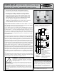
Figure 1. OPBX2 Series Power Blocks
in a Seriplex
®
stand-alone network
AC line
12V dc
Supply
Clock
Module
Each sensor output is given a unique
address, programmed via APC
hand-held programmer.
See APC literature for more
information on network requirements,
programming, clock modules, and
power supplies.
Quick Disconnect (QD) power block
OPBX2QD requires Banner XQDC
Series mating QD cable.
APC clock module
(see Specifications)
Network:
ring, loop-back,
bus, or star.
See Specifications.
BLACK (Common)
RED (+V dc)
GREEN (Clock)
WHITE (Data)
Model OPBX2 with
built-in cable or QD
model OPBX2QD.
Model OPBX2 with
built-in cable or QD
model OPBX2QD.
BARE (Shield)
BLACK (Common)
RED (+V dc)
GREEN (Clock)
WHITE (Data)
BARE (Shield)
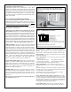
OPBX2QD
power block
OPBX2QD
with OSBD
sensor head
attached
APC
hand-held
progammer
OMNI-BEAM PHOTOBUS
™
OPBX2 Power Blocks
for use in APC Seriplex
®
programmable control systems
Printed in USA
P/N 34940H4A
NOTE: This data sheet is concerned primarily with
operating characteristics of Banner OMNI-BEAM
OPBX2 Series Power Blocks. For information about
the APC Seriplex
®
System itself, contact APC at:
106 Business Park Drive, Jackson, MS 39213
Tel (601) 956-2800 FAX (601) 956-9777
WARNING These photoelectric presence sensors do
NOT include the self-checking redundant circuitry necessary to
allow their use in personnel safety applications. A sensor failure
or malfunction can result in either an energized or a de-energized
sensor output condition.
Never use these products as sensing devices for personnel protec-
tion. Their use as safety devices may create an unsafe condition which could lead to
serious injury or death.
Only MACHINE-GUARD and PERIMETER-GUARD Systems, and other systems
so designated, are designed to meet OSHA and ANSI machine safety standards for
point-of-operation guarding devices. No other Banner sensors or controls are designed
to meet these standards, and they must NOT be used as sensing devices for personnel
protection.