
User Manual

Banner Engineering Corp. 9714 10th Ave. No., Minneapolis, MN 55441 Telephone: (612) 544-3164 FAX (applications): (612) 544-3573
MBC-4 MBCC-412
RF1-2NPS
Installation Information
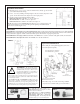
1) Mount the sensors exactly parallel to each other with their lenses directly opposite each other
(see Deadband Adjustment drawing).
2) Double check wiring carefully per Hookup Diagram. One sensor must be jumpered for "dark
operate", and the other must have the jumper removed for "light operate".
3) Operation checkout (using alignment indicator LEDs):
Both beams unblocked = both LEDs "on" and one output "on";
One beam blocked = one LED "off" and no output "on";
Both beams blocked = both LEDs "off" and the other output "on".
NOTE: if necessary, decrease SENSITIVITY (beneath lower cover; see drawing below, rotate
control counterclockwise) to prevent "burn-through" when guiding non-metallic materials
(and/or use model UC-D upper covers).
Typical Hookup Diagram
Accessories
Model SMB700 is a general-purpose two-axis mounting bracket which is supplied with a cable gland assembly that is used to attach the MULTI-
BEAM wiring base to the bracket. The gland assembly is threaded through the bracket and into the conduit entrance at the base of the scanner block.
A large lockwasher is supplied to hold the scanner block firmly in place. The bracket is 11-gauge zinc-plated steel.
Model SMB700SS is an 11-gauge stainless steel version of the SMB700. It is sold alone, without the cable gland assembly and lockwasher.
Model SMB700F is a flat, single-axis version of the SMB700. It is sold without hardware.
SMB700
!
WARNING This photoelectric presence
sensing system does NOT include the self-checking
redundant circuitry necessary to allow its use in
personnel safety applications. A sensor failure or
malfunction can result in either an energized or a de-
energized sensor output condition.
Never use this product as a sensing device for personnel protection. Its
use as a safety device may create an unsafe condition which could lead
to serious injury or death.
Only MACHINE-GUARD and PERIMETER-GUARD Systems, and
other systems so designated, are designed to meet OSHA and ANSI
machine safety standards for point-of-operation guarding devices. No
other Banner sensors or controls are designed to meet these standards, and
they must NOT be used as sensing devices for personnel protection.
*On-off delay, range 1-15 seconds; shorter ranges available
on a quote basis. See Banner catalog for more information.
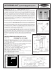
Spare Parts Identification
The modular parts of the Optical Edgeguide System can be
ordered and replaced separately.
*
Model RF1-2NPS cable gland assembly (left) for
MULTI-BEAMs includes cord grips for .1- to .4-inch
diameter cable and lockwasher.
Model MBC-4 (right) is a 4-pin male industrial
duty connector that threads into the base of all
MULTI-BEAMs. MBCC-412 is a 12-foot long
(3,6m) mini-type cable. It is interchangeable with
standard industry types of several manufacturers.