
User Manual
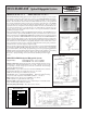

Functional Schematic, Optical Edgeguide System
DISTANCE
100
.1 FT 1 FT 10 FT
100 FT
1,000
10,00
0
100,00
0
Excess Gain,
MULTI-BEAM
Edgeguide System
E
X
C
E
S
S
G
A
I
N
I
Excess Gain Curve
®
The MULTI-BEAM Optical Edgeguide System is a unique sensor, used in pairs, to provide complete
edge-guidance sensing and control. Each sensor consists of a special MULTI-BEAM scanner block,
power block, and logic module. Each component is designed specifically for the edge-guiding
function. The scanner block, which contains a modulated emitter and receiver, works together with
the power block such that the emitter is gated "ON" only during positive half cycles of the 50/60Hz
power, and the receiver is gated "ON" only during the negative half cycles. The opposing sensor
operates the same way, except that it is wired with power leads L1 and L2 reversed from the way they
are connected to the first sensor. As a result, the sensor "A" emitter will only operate the sensor "B"
receiver, and vice-versa. This synchronization of the two sensors prevents unwanted crosstalk while
permitting very high excess gain.
The logic module includes both ON- and OFF-DELAY timing functions. The ON-DELAY ignores
short-term "nuisance" signals, and the OFF-DELAY permits a controlled amount of timed correction.
The logic modules have a LIGHT/DARK OPERATE programming jumper. Typically, the inboard
receiver is programmed for LIGHT OPERATE, and the outboard receiver for DARK OPERATE. In
this way, the web being guided is properly positioned in the "deadband" between the sensing beams
when one beam is broken and the other is not. The spacing between the beams is fixed at 1/2 inch (12,5
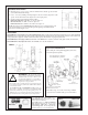
mm) and this becomes the "deadband" for edgeguiding. If tighter control is desired, the two sensors
may be mounted at an angle to the edge of the web such that the effective beam spacing is reduced to
1/2 inch times the cosine of the angle (see diagram at right).
The power block contains the same 3/4 amp solid-state switch as is used in standard MULTI-BEAM
power block models PBA and PBB, which will operate most ac solenoids, relays, or programmable
logic controllers (PLCs). The very high optical penetrating power (excess gain) plus rugged MULTI-
BEAM construction permits reliable control in harsh environments such as sawmills or power sanding
machines where conventional photoelectrics could not survive the contamination levels.
If necessary, optical penetrating power may be reduced by substituting model UC-D upper
covers.
Deadband Adjustment
Model 3GA5-14: 120V ac Model 3GB5-14: 220/240V ac
MULTI-BEAM Optical Edgeguide System
Dimension Drawing
SENSITIVITY control accessible beneath lower cover.
See drawing next page.
SPECIFICATIONS, Optical Edgeguide System
Supply Voltage: model 3GA5-14, 105 to 130V ac (50/60Hz)
model 3GB5-14, 210 to 250V ac (50/60Hz)
Output Configuration: SPST solid-state switch, 3/4 amp maximum (derated to 1/2 amp
at 70 degrees C). 10 amp maximum inrush for one second, or 30 amps for one ac cycle
(non-repeating). On-state voltage drop less than 2.5V ac at full load; off-state leakage
current less than 100 microamps.
Response Time: response time is a function of the ON and OFF delay timers, which are
independently adjustable over a useful range of from 1 to 15 seconds.
NOTE: shorter time ranges are available on a quote basis.
Construction: same as standard MULTI-BEAMs. Reinforced VALOX
®
housing;
components totally encapsulated. Meets NEMA standards 1, 3, 12, and 13.
Range: 100 feet (30 m). Excess gain of 10,000X at 1 foot (30 cm).
NOTE: materials to be guided must be totally opaque.
Indicator LED: red LED status indicator on top of the housing is "on" when the receiver
detects modulated light (unblocked) condition.
Operating Temperature Range: -40 to +70° C (-40 to +158° F).
Printed in USA
P/N 03506D5B