
User Manual
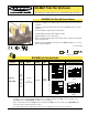

MINI-BEAM
®
Plastic Fiber Optic Sensors – DC Models
page 2
Banner Engineering Corp. • Minneapolis, U.S.A.
Website: http://www.baneng.com • Tel: 888.373.6767
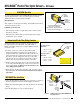
MINI-BEAM Operation
The sensor’s Gain adjustment and Light/Dark Operate switch are located
under the gasketed acrylic cover. Loosen the screw to access these
adjustments and use a small screwdriver to adjust.
Gain adjustment:
Turn clockwise to increase gain (sensitivity); 15-turn Gain potentiometer is
clutched at both ends of travel.
Light/Dark operate selection:
• Turn switch fully clockwise for light operate (sensor outputs conduct
when object is absent)
• Turn switch fully counterclockwise for dark operate (sensor outputs
conduct when object is present)
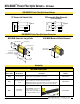
Unterminated Plastic Fiber Cutting Procedure
Unterminated plastic fibers are designed to be cut by the user to
the length required for the application. To facilitate cutting, a
Banner model PFC-1 cutting device is supplied with the fiber. Cut
the fiber as follows:
1) Locate the “control end” of the fiber (the unfinished end).
Determine the length of fiber required for the application. If
using a bifurcated fiber, separate the two halves of the fiber at
least 2" beyond the fiber cutting location. Lift the top (blade) of
the cutter to open the cutting ports. Insert one of the control
ends through one of the cutting ports on the PFC-1 cutter so
that the excess fiber protrudes from the back of the cutter.
2) Double-check the fiber length, and close the cutter until the fiber
is cut. Using a different cutting port, cut the second control end
to the required length. To ensure a clean cut each time, do not
use a cutting port more than once.
3) Gently wipe the cut ends of the fiber with a clean, dry cloth to remove
any contamination. Do not use solvents or abrasives on any exposed
optical fiber.
MINI-BEAM Fiber Installation
1) Unlock the fiber gripper as shown in figure 3. If 0.25 mm or 0.5 mm core
fibers are being used, insert the small fiber adapter into the ports.
2) Gently insert the prepared plastic fiber ends into the ports, as far as they
will go.
3) Slide the fiber gripper in to lock, as shown in figure 3.
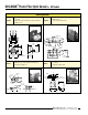
Figure 1. MINI-BEAM Plastic Fiber Optic sensor features
15 Turn
Sensitivity
Adjustment*
Gasketed
Acrylic Cover
Light/Dark
Operate Switch*
*Under acrylic cover
“AID” Indicator LED Lights when the
sensor sees its own modulated
light and pulses at a rate proportional to the
strength of the received light signal.
Trimmed fiber
control ends
Sensor face
Plastic fiber
emitter port
Plastic fiber
receiver port
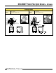
Unlock
Lock
Adapter for:
0.25 mm and
0.5 mm core
fibers
Figure 2. PFC-1 plastic fiber cutter (supplied with fiber)
Figure 3. Installing fibers into the MINI-BEAM Plastic
Fiber Optic sensor
Cutting Ports
4-Large
2-Small
Lift to Open Ports
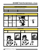
Use small ports for
fiber sizes:
• 0.25 mm = (0.01")
• 0.5 mm = (0.02")
Use large ports for
fiber sizes:
• 0.75 mm = (0.03")
• 1.0 mm = (0.04")
• 1.5 mm = (0.06")