
User Manual

MINI-BEAM
®
Sensors
SM2A312LV, SM2A312LVAG and SM2A312LP
page 2
MINI-BEAM Installation and Alignment
Proper operation of these sensors requires that they be mounted securely and aligned
properly. For best results, final-mount these sensors in an 18 mm hole by their threaded
barrel or use one of the available mounting brackets, (see pages 6 - 7).
1) Begin with the sensor at the desired distance from the retro target and at the
approximate position where it will be mounted. An object at the sensing
position should pass through the “core” of the sensor’s light beam.
2)
Switch the sensor to light-operate mode (see Note, below).
Apply power to the
sensor, and advance the sensor’s 15-turn GAIN control to maximum (clockwise
end of rotation). If the sensor is “seeing” the reflected light beam, the
alignment LED should be “on”. Move the sensor up-down-right-left to find the
center of the movement zone within which the LED indicator remains lit.
(Alternatively, the retro target may be moved.) Reducing the GAIN setting (if
necessary) will reduce the size of the movement zone and make more precise
alignment possible.
3) Repeat the alignment motions after each GAIN reduction. When you are
satisfied that you have obtained optimum alignment, mount the sensor (or
reflector) solidly in that position. Increase the receiver GAIN to maximum. Test
the system by placing the object to be detected into the sensing position. The
LED indicator should go “off”. (If it does, alignment is complete, and you may
now switch the sensor to dark-operate if the application requires it.) If the LED
of an “LV” model sensor does not go “off”, the sensor is reacting to light
reflected from the object (called “proxing”).
If proxing occurs, reduce the GAIN setting until the alignment indicator goes
“off”, plus two additional full turns. Remove the object from the sensing
position and check that the alignment indicator LED comes “on.” Confirm that
the LED goes “off” when the object is replaced.
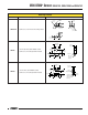
Proxing can be avoided by mounting the sensor so that it’s light beam is not
perpendicular to any flat reflective surface on the object to be detected (an
angle of 10 to 15 degrees is usually sufficient). Also, at distances of a few feet
or more, using more than one reflector may increase sensing contrast between
object-present and object-absent.
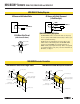
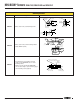
15 Turn
Gain
Adjustment
and Light/Dark
Operate Switch*
Gasketed
Acrylic Cover
Alignment indicator LED lights when the sensor's
output is conducting.
Up
Down
Left
Retro
Target
Retroreflective Mode Alignment
Move sensor (or target) to
obtain the fastest receiver LED
pulse rate.
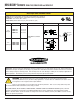
* Note regarding Light/Dark operate switch:
• Turn switch
fully
clockwise for light operate (sensor outputs conduct when object is absent)
• Turn switch
fully
counterclockwise for dark operate (sensor outputs conduct when object is present)