
User Manual
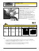

MINI-BEAM
®
Sensors
SM312D
page
2
Banner Engineering Corp. • Minneapolis, U.S.A.
www.bannerengineering.com • Tel: 763.544.3164
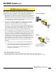
MINI-BEAM Installation and Alignment
Proper operation of the SM312D sensor requires that it be mounted securely and
aligned properly. Excessive movement or vibration can result in intermittent or false
operation caused by loss of alignment. For best results, final-mount the SM312D in
an 18mm-hole by its threaded barrel or use a mounting bracket (see page 6).
1) Begin with the sensor at the desired distance from the object to be sensed, and at the
approximate position where it will be mounted. The background should be as far
behind the object as possible (at least three times the distance of the sensor from the
object), and as dark a color as possible compared to the object. Ideally, the object
should present its largest reflective surface to the sensor.
2) Apply power to the sensor, and advance the 15-turn GAINcontrol to maximum
(clockwise end of rotation). The GAIN control is clutched at both ends to avoid
damage, and will “free-wheel” when either end point is reached.
If the sensor is “seeing” its reflected light, the sensor alignment LED should be “on”.
Move the sensor up-down-right-left (include angular rotation) to obtain the fastest
receiver LED pulse rate. If a pulse is not observable (too fast to count), reduce the
GAIN control(counterclockwise rotation) to obtain a countable pulse rate.
3) Repeat the alignment motions after each GAIN reduction. When you have found the
sensor orientation that produces the fastest pulse rate, mount the sensor solidly in
that position. Increase the receiver GAINto maximum. Test the system by removing
the object from the sensing position. The receiver LED indicator should go “off”. If
the LED indicator does not go “off”, the sensor is reacting to light reflected from a
background surface. Reduce the GAIN setting until the alignment indicator goes “off”,
plus two additional full turns. Again place the object in the sensing position. If the
alignment indicator does not come “on”, the sensor is receiving as much or more
light energy from the background as from the object. Consider the following
alternatives:
a) move the sensor closer to the object and reduce the sensitivity (GAIN);
b) reduce background reflectivity by painting the background with flat-black
paint, or by scuffing the background or cutting a hole through it;
c) tilt the sensor or the background so that the sensing beam is not
perpendicular to the background.
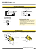
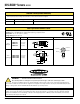
15 Turn
Gain
Adjustment
and Light/Dark
Operate Switch*
Gasketed
Acrylic Cover
“AID” Indicator LED Lights when the
sensor sees its own modulated
light and pulses at a rate proportional to the
strength of the received light signal.
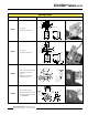
O
bject
U
p
D
ow
n
Left
R
ight
SM312D
Diffuse Mode Alignment
SM312D
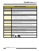
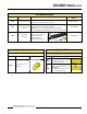
* Note regarding Light/Dark operate switch:
• Turn switch fully clockwise for light operate (sensor outputs conduct when sensing light is received)
• Turn switch fully counterclockwise for dark operate (sensor outputs conduct when sensing light is not received)