t ns uc tio od ca Pr ne ifi Li pec S MAXI-BEAM® Sensors Highly versatile modularized photoelectric sensing controls Printed in USA • Highly versatile, self-contained, modularized photoelectric sensors; especially suited to industrial environments • Wide selection of rotatable sensor heads, power blocks, and logic timing modules to suit any application • Power blocks for AC or DC operation and for switching of AC or DC loads • Sensor heads include patented AID™ indicator device, which lights a top
MAXI-BEAM® MAXI-BEAM™ Sensor Heads Modular Sensors Banner MAXI-BEAM sensors are highly versatile, self-contained, modularized photoelectric sensing controls that are ideally suited to industrial environments. The basic MAXI-BEAM is an ON/OFF switch consisting of three modules: a sensor head, a power block, and a wiring base. The sensor head contains the complete modulated photoelectric amplifier as well as the emitter and receiver optoelements.
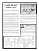
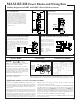
Selection of MAXI-BEAM Components The modular design of the MAXI-BEAM allows you to create a sensor which is tailored to your exact requirements. To order a MAXI-BEAM, follow these steps: Exploded view, MAXI-BEAM Sensor Sensitivity Control 1) SELECT A SENSOR HEAD (see pages 3-7). Sensor heads are available for opposed, retroreflective, diffuse, convergent, and fiberoptic sensing modes. Rotatable Sensor Head 2) SELECT A POWER BLOCK (see pages 8-13).
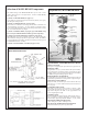
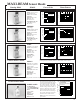
MAXI-BEAM Sensor Heads Sensing Mode Models RSBE & RSBR OPPOSED Mode Beam Pattern Excess Gain 1000 Range: 300 feet (90 m) in RSBE/RSBR RSBE/RSBR 15 "HP" (high power) and 2W E 10 (2 wire) modes X 100 HP, 2W I HS C N 5 Beam: infrared, 880nm; E SP HP, 2W HS C 0 S H visible red tracer beam S SP E S 5 Effective Beam: 0.5" dia. G 10 10 A Response: II 15 N HP, 2W mode: 10ms on/ 80 160 240 320 400 0 5 off 1 OPPOSED DISTANCE --FE 1 FT 10 FT 100 FT 1000 FT HS mode: 1ms on/0.5 off DISTANCE SP mode: 0.
MAXI-BEAM Sensor Heads Sensing Mode Models RSBD Range: 5 feet (1,5 m) in HP and 2W modes Beam: infrared, 880nm Response: HP, 2W modes: 10ms HS mode: 1ms SP mode: 0.3ms Repeatability: HP, 2W= 3.3ms; HS = 0.3ms; SP = 0.1ms DIFFUSE Mode RSBDSR (short range) Range: 30 inches (76cm) in HP and 2W modes Beam: infrared, 880nm Response: HP, 2W modes: 10ms HS mode: 1ms SP mode: 0.3ms Repeatability: HP, 2W= 3.3ms; HS =0.3ms; SP =0.1ms 1000 CONVERGENT Mode RSBCV Focus at 1.5 in.
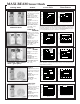
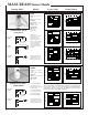
MAXI-BEAM Sensor Heads Sensing Mode Models RSBF Range: see excess gain curves Beam: infrared, 880nm Response: HP, 2W modes: 10ms HS mode: 1ms SP mode: 0.3ms FIBER OPTIC Mode (glass fibers) OPPOSED MODE RETRO MODE OBJECT RETROREFLECTOR Repeatability: HP, 2W= 3.3ms; HS = 0.3ms; SP = 0.1ms NOTE: if the retroreflective sensing mode is used in conjunction with the HP or 2W program mode, the GAIN control must be reduced from the factory setting in order to avoid optical feedback from the lens assembly.
MAXI-BEAM Sensor Heads Sensing Mode RSBFV Range: see excess gain curves Beam: visible red, 650nm. Response: HS mode only, 1ms on/off Repeatability: HS = 0.3ms FIBER OPTIC Mode (glass fibers) OPPOSED MODE OBJECT RETROREFLECTOR RETRO MODE OBJECT DIFFUSE MODE OBJECT Excess Gain Models The model RSBFV will function only when programmed for the "HS" response mode. The model RSBFV will not operate with 2-wire power blocks (models R2PBA and R2PBB).
MAXI-BEAM Power Blocks and Wiring Base MAXI-BEAM power blocks provide regulated low voltage dc power to the sensor head and logic module (if one is used), and all power blocks (except emitter-only types) contain an output switch for interfacing to loads or to control circuitry. Power blocks plug into the model RWB4 wiring base which has heavy-duty screw terminals that accept up to #12 gauge wire (no lugs are necessary).
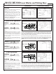
MAXI-BEAM Power Blocks and Wiring Base Hookup Diagrams for RPBT and RPBT-1 Power Blocks (continued) Parallel Hookup of RPBT Power Blocks to a Common Load Hookup of a DC Emitter 10 - 30V dc MAXI-BEAM emitter only sensor heads use dc power block model RPBT-1, which connects directly across the dc supply as shown. Any number of MAXI-BEAMs may be connected in parallel to a load to create "LIGHT-OR" (light operate mode) or "DARK-OR" (dark operate mode) multiple sensor logic.
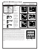
MAXI-BEAM Power Blocks and Wiring Base AC Models Functional Schematic Connections RPBR2 INPUT: 12 to 30V dc, 40mA, exclusive of load current (at 30V dc); or 12 to 250V ac, 50/60Hz. OUTPUT: SPDT electromechanical relay contacts. Contact rating: 250V ac max., 30V dc max., 5 amps max. (resistive load); install MOV across contact if switching inductive load. Contact response: 20ms open and close (NOTE: add to sensor head response). Mechanical life: 10,000,000 operations.
MAXI-BEAM Power Blocks and Wiring Base Hookup Diagrams for RPBA, RPBA-1, RPBB, & RPBB-1 Power Blocks Hookup to a Simple Load L1 L Hookup of an ac Emitter 2 V ac (See Specifications) AC voltage is connected to terminals #1 and #2 to provide power to the MAXI-BEAM. The solid-state output switch behaves as if there were a contact between terminals #3 and #4. L1 is most conveniently applied to terminal #3 by jumpering terminals #1 and #3 inside the wiring base.
MAXI-BEAM Power Blocks and Wiring Base Hookup Diagrams for R2PBA and R2PBB Power Blocks Basic 2-wire Hookup 2-wire MAXI-BEAMs in Parallel L1 L Multiple 2-wire MAXI-BEAMs may be wired together in parallel to a load for "OR" or "NAND" logic functions. When sensors are wired in parallel, the off-state leakage current through the load is equal to the sum of the leakage currents of the individual sensors.
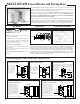
MAXI-BEAM Power Blocks Model RPBTLM Low Profile DC Power Block Model RPBTLM is a miniature dc power block for MAXI-BEAM sensors. It may be used with any of the MAXI-BEAM sensor head models. The RPBTLM is supplied with stainless steel hardware used for assembly of the MAXI-BEAM components. Components simply bolt together, with no interwiring necessary. The screws supplied are extra-long, and serve as a means to mount the complete MAXI-BEAM sensor assembly to an object or surface.
MAXI-BEAM Logic Modules MAXI-BEAM sensors offer built-in timing logic with the addition of a logic module. There are two logic modules available. Model RLM5 is programmable for ON-DELAY, OFFDELAY, and ON/OFF DELAY timing logic. Model RLM8 offers both ONE-SHOT and DELAYED ONE-SHOT functions. A programming ring is supplied with each logic module. Programming of the logic function, timing range, and output state is similar to sensor head programming.
MAXI-BEAM Logic Modules Programming Model and Logic Functions RLM8 PROGRAM CHOICES: 1) Timing Logic Function: a) ONE-SHOT b) Delayed ONE-SHOT 2) Timing Adjustment Range (see options below) 3) Output State: a) normally open b) normally closed TO PROGRAM LOGIC MODULE: 1) Find the programming notch which lines up with the program choice. NOTE: the programming ring may have to be turned upside-down in order to find a notch that lines up with the desired program.
MAXI-BEAM Accessories Mounting Brackets Model SMB700 (right) is a general-purpose two-axis mounting bracket that is supplied with a cable gland assembly which is used to attach the MAXI-BEAM wiring base to the bracket. The gland assembly is threaded through the bracket and into the conduit entrance at the base of the scanner block. A large lockwasher is supplied to hold the scanner block firmly in place. The bracket is 11-gauge zinc plated steel.