
Engineering Light Gauging Sensors Product Brochure

More information online at bannerengineering.com
301
MEASUREMENT & INSPECTION
TEMPERATURE
ULTRASONIC
LIGHT
GAUGING
RADAR
MEASURING LIGHT
SCREENS
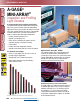
A-GAGE
®
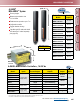
MINI-ARRAY
®
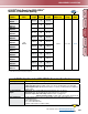
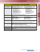
Sensor Specifications
Emitter/Receiver Range
Max range is specied at the point
where 3x excess gain remains.
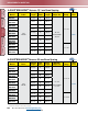
9.5 mm beam spacing 19.1 mm beam spacing
Array Length 143 to 1057 mm: 0.6 to 6.1 m Array Length 133 to 1057 mm: 0.9 to 17 m
Array Length 1210 to 1819 mm: 0.6 to 4.6 m Array Length 1200 to 1810 mm: 0.9 to 14 m
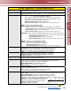
Minimum Object Sensitivity
9.5 mm Beam Spacing 19.1 mm Beam Spacing
Straight, Edge Modes: 19.1 mm Straight, Edge Modes: 38.1 mm
Interlaced Mode: 12.7 mm* Interlaced Mode: 25.4 mm*
With DeviceNet Controller: With DeviceNet Controller:
Straight, Edge Modes: 19.1 mm Straight, Edge Modes: 38.1 mm
Skip Mode: Multiply the above by the Skip Mode: Multiply the above by the
number of skipped beams, plus 1 number of skipped beams, plus 1
Interlaced Mode: 12.7 mm* Interlaced Mode: 25.4 mm*
*Assumes sensing is in the middle 1/3 of sensing range.
Sensor Scan Time
55 microseconds per beam, plus 1 millisecond post process time per scan.
DeviceNet: Post process time will vary, based on the number of channels interrogated during each scan.
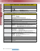
Power Requirements
†
Maximum current is for a 6' sensor.
9.5 mm beam spacing 19.1 mm beam spacing
12V dc ±2%, supplied by controller 12V dc ±2%, supplied by controller
Emitter: 0.10 A @ 12V dc Emitter: 0.10 A @ 12V dc
Receiver: 0.75 A @ 12V dc
†
Receiver: 0.50 A @ 12V dc
†
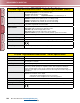
Connections
Sensors connect to controller using 5-conductor Mini-style quick-disconnect cables (one each for
emitter and receiver), ordered separately. Use only Banner cables, which incorporate a “twisted pair”
for noise immunity. Cables measure 8.1 mm dia. and are shielded and PVC-jacketed. Conductors are
20 gauge. Emitter and receiver cables may not exceed 75 m long, each. See page 421.
Status Indicators
Emitter: Red LED lights to indicate proper emitter operation
Receiver: Green indicates sensors aligned (> 3x excess gain)
Yellow indicates marginal alignment of one or more beams (1x -3x excess gain)
Red indicates sensors misaligned or one or more beam(s) blocked
Construction
Aluminum, with black anodized nish; acrylic lens cover
Environmental Rating
NEMA 4, 13; IP65
Operating Conditions
Temperature: -20° to +70° C Relative humidity: 95% at 50° C (non-condensing)