
Engineering Light Gauging Sensors Product Brochure

278 More information online at bannerengineering.com
COLOR &
lUMINESCENCE
PICK-TO-LIGHT
SLOT & LABEL
MEASUREMENT & INSPECTION
MEASURING LIGHT
SCREENS
TEMPERATURE
LIGHT
GAUGING
RADAR
ULTRASONIC
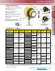
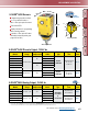
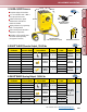
U-GAGE
®
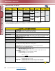
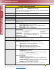
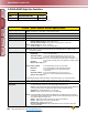
Q45U Specifications
Sensing Range
Near limit: 100 mm min. Long Range: Near limit: 250 mm min.
Far limit: 1.4 m max. Long Range: Far limit: 3.0 m max.
NOTE: The far limit may be extended on long range units, as far as 3.9 m for good acoustical targets
(hard surfaces with area greater than 100 cm
2
)
Supply Voltage and Current
Discrete: 12 to 24V dc (10% max. ripple); 100 mA (exclusive of load)
Analog: 15 to 24V dc (10% max. ripple); 100 mA (exclusive of load)
Ultrasonic Frequency
Long Range: 128 kHz Short Range: 230 kHz
Supply Protection Circuitry
Protected against reverse polarity and transient voltages.
Output Protection Circuitry
Protected against false pulse on power-up and continuous overload or short-circuit of outputs.
Output Configuration
Discrete: Bipolar: One current sourcing (PNP) and one current sinking (NPN) open-collector transistor.
Analog: One voltage sourcing and one current sourcing; one or the other output is enabled by internal
programming switch #2.
Output Ratings
Discrete: 150 mA max. (each)
OFF-state leakage current: less than 25 µA at 24V dc
ON-state saturation voltage: less than 1.5V at 10 mA; less than 2.0V at 150 mA
Analog: Voltage sourcing: 0 to 10V dc, 10 mA max.
Current sourcing: 4 to 20 mA, 1 to 500 Ω impedance
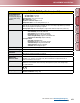
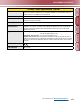
Performance Specifications
Short Range Long Range
Analog resolution or
discrete repeatability: ± 0.1% of sensing distance ± 0.1% of sensing distance
(± 0.25 mm min.) (± 0.5 mm min.)
Analog Linearity: 1% of full scale 1% of full scale
Temperature effect: 0.05% of sensing distance/ ° C with temp. comp. 0.05% of sensing distance/° C
0.2% of sensing distance/ ° C without temp. comp.
Min. window size: 10 mm 25 mm
Hysteresis (discrete output): 5 mm 10 mm
Response Curves
Short Range: See charts RC-2 and RC-4 on page 516.
Long Range: See charts RC-3 and RC-5 on page 516.
Adjustments
The following may be selected by a 4-position DIP switch located on top of the sensor, beneath a
transparent o-ring sealed acrylic cover:
Discrete: Switch 1: Output normally open/normally closed (pump in/pump out)
Switch 2: High/Low level control mode or ON/OFF presence sensing mode
Switch 3 & 4: Response speed selection (digital lter)
Analog: Switch 1: Output slope positive or output slope negative
Switch 2: Current output mode or voltage output mode
Switch 3: Loss of echo min/max mode or loss of echo Hold Mode
Switch 4: Loss of echo min/max default output value
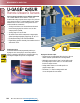
Indicators
Discrete: Three status LEDs:
Green ON steady: power to sensor is ON
Green flashing: output is overloaded
Yellow ON steady: outputs are conducting (Yellow LED also indicates programming
status during setup mode)
Red flashing: indicates relative strength of received echo
Analog: Three status LEDs:
Green ON steady: power to sensor is ON
Green flashing: current output fault detected (the 4-20 mA current path to ground has
been opened)
Yellow ON steady: target is sensed within the window limits (Yellow LED also indicates
programming status during setup mode)
Red flashing: indicates relative strength of received echo
5-segment moving dot LED indicates the position of the target within the sensing window.
More on
next page