
Engineering Light Gauging Sensors Product Brochure

More information online at bannerengineering.com
255
MEASURING
LIGHT SCREENS
TEM PER AT URE
ULTRASONIC
MEASUREMENT & INSPECTION
RADAR
LIGHT
GAUGING
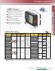
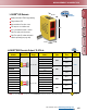
L-GAGE
®
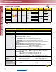
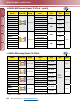
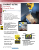
LG5 and LG10 Specifications
Minimum Window Size
(Analog or Discrete)
LG5: 1.5 mm LG10: 5 mm
Discrete Output Hysteresis
LG5: Less than 0.2 mm LG10: Less than 1.0 mm
Color Sensitivity (typical)
LG5: Less than 75 µm LG10: Less than 100 µm
for white to dark gray ceramic target for white to dark gray ceramic target
Temperature Effect
LG5: +/- 7 µm/° C LG10: +/- 25 µm/° C
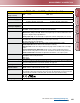
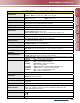
Remote TEACH and Laser
Control Input Impedance
18 kΩ min. (65 kΩ min. at 5V dc)
Remote TEACH
To teach: Connect yellow wire to +5 to 30V dc
To disable: Connect yellow wire to 0 to +2V dc (or open connection)
Adjustments
Response speed: Push button toggles between Slow, Medium, and Fast (see Output Response Time)
Window limits (analog or discrete): TEACH-mode programming of near and far window limits. Limits
may also be taught remotely using TEACH wire.
Analog output slope: The first limit taught is assigned to the minimum analog output (0V dc or 4 mA).
Laser Control
To enable laser: Connect green wire to +5 to 30V dc
To disable laser: Connect green wire to 0 to +2V dc (or open connection)
250 millisecond delay upon enable/disable
Indicators
Green Power ON LED: Indicates when power is ON, overloaded output and laser status.
Yellow Output LED: Indicates when discrete load output is conducting.
Red Signal LED: Indicates when target is within sensing range and the condition of the received light
signal.
Tri-color Red/Green/Yellow TEACH LED: Indicates sensor is ready for programming each limit
(indicates Red for analog output, Green for discrete, and Yellow for simultaneous analog and discrete.)
Yellow Fast/Slow LEDs: Combination of 2 lights ON or OFF indicates 1 of 3 response speeds
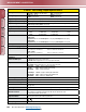
Construction
Housing: Zinc alloy die-cast, plated and painted finish
Cover plate: aluminum with painted finish
Lens: acrylic
Environmental Rating
IP67; NEMA 6
Connections
2 m or 9 m 7-conductor shielded PVC-jacketed attached cable, or 150 mm 8-pin Euro-style pigtail quick-
disconnect. Mating QD cables are purchased separately. See page 416.
Operating Conditions
Temperature: -10° to +50° C Relative humidity: 90% at 50° C (non-condensing)
Vibration and
Mechanical Shock
Vibration: 60 Hz, 30 minutes, 3 axes
Shock: 30G for 11 milliseconds, half sine wave, 3 axes
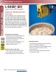
Application Notes
For comparison, a white ceramic test surface has approximately 91% of the reflectivity of a white Kodak
test card with a matte finish. A dark gray ceramic test surface has approximately 11% of the reflectivity of
a white Kodak test card with a matte finish. (Allow 15-minute warm-up for maximum linearity.)
Certifications
Hookup Diagrams
NPN Models: MI06 (p. 533) PNP Models: MI07 (p. 533)
(cont’d)