
Safety Light Curtain Systems Owner's manual


6 P/N 68413 rev. A
Banner Engineering Corp. • Minneapolis, U.S.A.
www.bannerengineering.com • Tel: 763.544.3164
EZ-SCREEN Point
Instruction Manual
Overview
If trip output is selected, the OSSD outputs will turn ON after
power is applied, and the receiver passes its internal self-test/
synchronization and recognizes that the beam is clear. The trip
output will also automatically reset after all beam interruptions
are cleared. If latch output is selected, the EZ-SCREEN requires
a manual reset for the OSSD outputs to turn ON, after power is
applied and the beam is clear (see Section 4.2.1).
External Device Monitoring (EDM)
This feature allows the EZ-SCREEN Point to monitor the
status of external devices, such as MPCEs. The choices are
one- or two-channel monitoring, or OFF. EDM is used when the
EZ-SCREEN Point OSSD outputs directly control the energizing
and de-energizing of the MPCEs or other external devices; see
Sections 3.7.3 and 4.1 for more information.
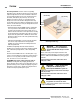
Remote Test Input
A pair of terminals is provided at the emitter (see Section
3.7.4) for an external switch, typically a normally open contact
held closed. Opening a switch connected between these two
terminals “turns off” the emitter, simulating an interruption of the
beam. This remote test input may be useful for EZ-SCREEN
Point system setup and to verify machine control circuit
operation.
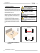
Scan Code Configuration
The emitter and receiver may be configured to one of two
scan code positions (1 or 2). Scan codes enable a receiver
to recognize the beam only from an emitter with the same
scan code setting. This helps minimize the effects of crosstalk
between multiple emitter/receiver pairs, and allows multiple pairs
to operate in close proximity in certain situations. See Section
3.3 for proper mounting configurations. The scan code is set
using the selection switch in each sensor’s configuration port;
see Section 4.1 for more information. Both the emitter and its
corresponding receiver must be set to the identical setting
.
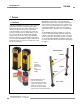
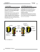
Status Indicators
A variety of status indicators on both the system emitter and
receiver are clearly visible on each sensor’s front panel.
• Emitter: A single bi-color red/green Status indicator shows
whether power is applied, and whether the emitter
is in Run mode, Test mode, or Lockout mode. A
7-segment diagnostic display indicates specific
error or configuration conditions.
• Receiver: A bi-color red/green Beam Status indicator shows
whether the beam is aligned and clear with a
strong signal, clear but with a weak signal, or is
blocked and/or misaligned. A yellow Reset
indicator shows when the system is in Run mode
or is waiting for a reset. A bi-color red/green
Status indicator shows when outputs are ON or
OFF, or the system is in lockout mode. A
7-segment diagnostic display indicates specific
error or configuration conditions.
See Section 4.3 for more information about specific indicator and
diagnostic display code meanings.