
Safety Light Curtain Systems Owner's manual


P/N 68413 rev. A 5
Banner Engineering Corp. • Minneapolis, U.S.A.
www.bannerengineering.com • Tel: 763.544.3164
EZ-SCREEN Point
Instruction Manual
Overview
1.3 Control Reliability
In addition to physical location requirements, safety standards
require a safety system such as the EZ-SCREEN Point to
fulfill some internal requirements. For example, for an optical
safety system to be used in a Safety Category 4 application
(per EN954-1), it must be third-party certified to the type 4
requirements of IEC 61496-1 and -2.
EZ-SCREEN Point’s microprocessor-based circuitry features
a “diverse-redundant” design, in which two microprocessors
of different design, running from different instruction sets,
constantly check all system components, including each other.
In addition, EZ-SCREEN Point is extensively FMEA (Failure
Mode and Effects Analysis) tested to establish an extremely
high probability that no system component will ever (even if it
does fail) cause a failure to danger.
BEAMS
1
2
R
E
S
E
T
S
T
A
T
U
S
SCAN
CODE
2
1
BEAMS
1
2
R
E
S
E
T
S
T
A
T
U
S
EZ-SCREEN Point
BANNER ENGINEERING CORP., USA
888.373.6767
STATUS
SCAN
CODE
2
1
1
1
ON
2 3 4
SCAN
CODE
2
1
T
L
1
2
T
L
1
E
D
M
E
D
M
2
S
T
A
T
U
S
BEAM
R
E
S
E
T
S
T
A
T
U
S
EZ-SCREEN Point
BANNER ENGINEERING CORP., USA
888.373.6767
E
D
M
E
D
M
2 T 1 T 1
1 L 2 L 2
SCAN
CODE
BEAM
R
E
S
E
T
S
T
A
T
U
S
EZ-SCREEN Point
BANNER ENGINEERING CORP., USA
888.373.6767
ReceiverEmitter
STATUS
EZ-SCREEN Point
BANNER ENGINEERING CORP., USA
888.373.6767
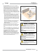
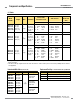
Scan Code
Select Switch
Scan Code
Select Switch
Beam Status Indicator –
Bi-color Red/Green
Trip/Latch and EDM
Select DIP Switches
7-Segment
Diagnostic Display
7-Segment
Diagnostic Display
Reset Indicator –
Yellow
Status Indicator –
Bi-color Red/Green
Status Indicator –
Bi-color Red/Green
Wiring Chamber
End Cap
Configuration
Access Port
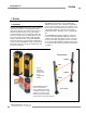
Figure 1-5. EZ-SCREEN features
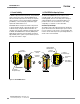
1.4 EZ-SCREEN Point Operating Features
The Banner EZ-SCREEN Point System features several
selectable functions: trip or latch output, external device
monitoring (EDM), and scan code setting. These settings are
configured within the sensors, behind the threaded access
port on the front of each sensor and in the sensor wiring
configuration; see Section 4.1 for more information.
Selectable Trip/Latch Output
The setting for latch or trip output also determines whether the
System will enter Run mode automatically or require a manual
reset (see Section 4.1). If the system is set for trip output, other
measures must be taken to prevent a pass-through hazard; see
Section 3.3.3 for more information.