
Safety Light Curtain Systems Owner's manual


50 P/N 68413 rev. A
Banner Engineering Corp. • Minneapolis, U.S.A.
www.bannerengineering.com • Tel: 763.544.3164
EZ-SCREEN Point
Instruction Manual
Periodic Checkout Procedures
6.3 Commissioning Checkout
Perform this checkout procedure as part of System
installation (after the System has been interfaced to
the guarded machine as described in Section 3.7), or
whenever changes are made to the System (either a new
configuration of the EZ-SCREEN System or changes to
the machine). A Qualified Person (as defined in the Safety
Glossary) must perform the procedure; checkout results should
be recorded and kept on or near the guarded machine, per
OSHA 1910.217(e)(1).
To prepare the System for this checkout, set the System
configuration as it will be during machine operation.
1. Examine the guarded machine to verify that it is of a type
and design compatible with the EZ-SCREEN System. See
page 2 for a list of misapplications.
2. Verify that the minimum separation distance from the closest
danger point of the guarded machine to the light beam(s) is
not less than the calculated distance, per Section 3.3.1 of
this manual.
3. Verify that
• Access to any dangerous parts of the guarded machine
is not possible from any direction not protected by the
EZ-SCREEN System, hard guarding, or supplemental
safeguarding, and
• It is not possible for a person to stand between the light
beams(s) and the dangerous parts of the machine, or
• Supplemental safeguarding and hard guarding, as
described by the appropriate safety standards, are in place
and functioning properly in any space between the light
beams(s) and any hazard which is large enough to allow a
person to stand undetected by the EZ-SCREEN System.
4. Verify that the Reset switch is mounted outside the guarded
area, out of reach of anyone inside the guarded area, and
that the key or other means of preventing inadvertent use is
in place.
5. Examine the electrical wiring connections between the
EZ-SCREEN System OSSD outputs and the guarded
machine’s control elements to verify that the wiring meets the
requirements stated in Section 3.7.
6. Inspect the area near the light beam(s) (including work
pieces and the guarded machine) for reflective surfaces.
(Reflective surfaces may cause light to reflect around a
person in the beam, preventing the person from being
detected and not stopping the machine motion.) Remove the
reflective surfaces as possible by relocating them, painting,
masking or roughening them. Remaining problem reflections
will become apparent during step 10.
7. Apply power to the EZ-SCREEN System. Ensure that power
to the guarded machine is OFF. Remove all obstructions from
the light beam. If the System is configured for Latch mode,
the receiver Reset indicator will be double-flashing. Perform
a manual reset (close the Reset switch for 1/4 to 2 seconds,
then open the switch). Verify that the Reset indicator is ON
steady.
8. Observe the receiver 7-segment display to verify that the
System is set to the desired output mode (Trip Output - “–”;
Latch Output - “L”).
Observe the status indicators on the receiver to determine
System status:
A blocked condition is indicated by the Status indicator
steady Red, and the Beam Status indicator steady Red.
A clear condition is indicated by the Beam Status indicator
steady Green. (It will flicker Green if excess gain is marginal.)
A latch condition is indicated by the receiver Status
indicator steady Red. The Beam Status indicator may be
Red, Green, or flashing Green, depending on beam status. In
Latch Output mode, the outputs come back ON only when the
beam is clear and after a manual reset.
A lockout condition is indicated by the Status indicator
single-flashing Red, and the Reset indicator OFF.
9. If in a clear condition, go to step 10. If in a lockout condition,
refer to Section 5. A blocked condition indicates that the beam
is misaligned or interrupted. To correct this situation:
a. Check carefully for any obstruction in the path of the
beam.
b. Check for contamination. Clean the emitter and receiver
windows as required (see Section 5.4).
c. If the beam is completely clear of obstructions, realign the
emitter and receiver, as described in Section 3.6.
If the System is in a latch condition, perform a manual reset.
10. Once the System Status and Beam Status indicators are
steady Green, perform the trip test (described in Section
6.2) to verify proper System operation and to detect possible
reflection problems.
11. Apply power to the guarded machine and verify that the
machine does not start up. Block the beam and verify that it
is not possible for the guarded machine to be put into motion
while the beam is blocked.
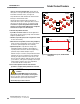
12. Initiate machine motion of the guarded machine and, while it
is moving, use the supplied test piece to block the beam. Do
not attempt to insert the test piece into the dangerous parts
of the machine. Upon blocking the beam, the dangerous
parts of the machine should come to a stop with no apparent
delay. Upon removal of the test piece from the beam, verify
that the machine does not automatically restart, and
that the initiation devices must be engaged to restart the
machine.