
Safety Light Curtain Systems Owner's manual


P/N 68413 rev. A 3
Banner Engineering Corp. • Minneapolis, U.S.A.
www.bannerengineering.com • Tel: 763.544.3164
EZ-SCREEN Point
Instruction Manual
Overview
1.2 Applications and Limitations
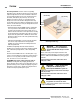
The Banner EZ-SCREEN Point System is designed for use
in access-guarding and perimeter-guarding applications. It is
designed to be installed in multiple sensor pairs, with the beams
stacked vertically, in order to detect a body or torso (rather than
a hand or an arm) as a person enters a hazardous area. It is not
intended nor designed for hand or finger detection in point-of-
operation applications. See Figure 1-2.
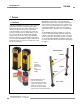
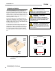
In perimeter-guarding and access-guarding applications, the
light beams are positioned to create a vertical or nearly vertical
“light grid.” In these applications, personnel typically can pass
through the light grid (which removes or stops the hazard), then
may continue into the hazardous area.
A recommended set of beam placement positions has become
accepted in the United States and Europe. The standards
(ANSI/RIA R15.06, ANSI B11 and EN 999) recommend a safe
beam placement, in order to hinder personnel from crawling
over, under or through the light grid, and into the hazardous
area, without detection. For more information, refer to Section
3.3.1.
WARNING . . .
Not for Point-of-
Operation or Area Guarding
Do not use the EZ-SCREEN Point System for hand
or finger detection in point-of-operation applications.
WARNING . . .
Proper Beam
Configuration
The beam configuration of EZ-SCREEN Point
Systems must meet the requirements of applicable standards
for each application. It is the user’s responsibility to verify
proper beam configuration.
Figure 1-2. EZ-SCREEN Point perimeter-guarding application
— a vertical configuration of two beams (long-
range emitters)
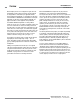
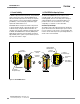
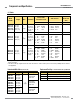
Figure 1-3. Selecting the proper emitter
Emitter SPE1
Short-Range Emitter
Long-Range Emitter
Receiver
0.8 to 20 m
(2.6' to 65')
Emitter SPXLE1 Receiver
15 to 70 m
(49' to 230')
Vertical
Corner
Mirrors
Vertical
Corner
Mirrors
CAUTION . . .
Proper Model Selection
Ensure proper selection of emitter models, with
respect to range (operating distance) between emitter
and receiver, to minimize the possibility of optical short circuits (see
Sections 2.1 and 3.3.4).