
Safety Light Curtain Systems Owner's manual

40 P/N 68413 rev. A
Banner Engineering Corp. • Minneapolis, U.S.A.
www.bannerengineering.com • Tel: 763.544.3164
EZ-SCREEN Point
Instruction Manual
Operating Instructions
Operating
Mode
Required
Event
Reset
Indicator
Status
Indicator
Beam Status
Indicator
Diagnostic Display
OSSD
Outputs
Power-up Apply Power OFF
Single-Flash
Red
Single-Flash
Red
Scan code flash 3x
(C1 or C2)
OFF
Alignment Mode –
Beam Blocked
Passes Internal
Tests
OFF OFF Red OFF OFF
Alignment Mode –
Beam Clear
Align Beam
Double-
Flash
OFF Green
(1)
OFF OFF
Run Mode –
Clear
Perform Reset ON Green Green
(1)
“L” ON
Latched
– Blocked
Beam Blocked ON Red Red “L” OFF
Latched – Clear Clear Beam Flashing Red Green
(1)
“L” OFF
Lockout Mode
Internal/External
Fault
OFF Flashing Red OFF Displays Error Code
*
Operating
Mode
Required
Event
Reset
Indicator
Status
Indicator
Beam Status
Indicator
Diagnostic Display
OSSD
Outputs
Power-up Apply Power OFF
Single-Flash
Red
Single-Flash
Red
Scan code flash 3x
(C1 or C2)
OFF
Alignment Mode –
Beam Blocked
Passes Internal
Tests
OFF OFF Red OFF OFF
Run Mode –
Clear
Align Beam ON Green Green
(1)
Dash ON
Run Mode –
Blocked
Beam Blocked ON Red Red Dash OFF
Run Mode –
Blocked
Internal/External
Fault
OFF Flashing Red OFF Displays Error Code
*
OFF
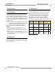
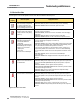
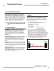
Receiver: A bi-color red/green Beam Status indicator shows
whether the beam is aligned and clear with a strong signal,
clear but with a weak signal, or is blocked and/or misaligned. A
yellow Reset indicator shows when the System is in Run mode
or is waiting for a reset. A bi-color red/green Status indicator
shows when the OSSD outputs are ON (green) or OFF (red),
or the System is in lockout mode (flashing red). A 7-segment
diagnostic display indicates the receiver’s Trip (–) or Latch (L)
output configuration setting and displays a specific error code
when the receiver is in lockout. The 7-segment display also
momentarily indicates the scan code setting at power-up or
when changed.
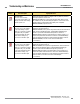
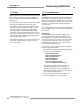
Figure 4-3a. Receiver status indicators and operation (Trip Output mode)
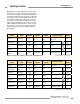
Figure 4-3b. Receiver status indicators and operation (Latch Output mode)
* See Section 5.1 for a description of error codes
(1)
Flashing Green indicates a clear but weak signal.
* See Section 5.1 for a description of error codes
(1)
Flashing Green indicates a clear but weak signal.