
Safety Light Curtain Systems Owner's manual

P/N 68413 rev. A 39
Banner Engineering Corp. • Minneapolis, U.S.A.
www.bannerengineering.com • Tel: 763.544.3164
EZ-SCREEN Point
Instruction Manual
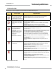
Operating Instructions
Operating
Mode
Required
Event
Status
Indicator
Diagnostic
Display
Power-up Apply Power Red Single
Flash
Scan code
flash 3x
(C1 or C2)
Run Mode Passes
Internal Tests
Green Dash
Test Mode Open Test
Switch
Flashing
Green
Dash
Lockout
Mode
Internal/
External Fault
Flashing
Red
Displays
Error Code
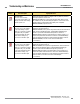
4.2 Reset Procedures
4.2.1 Receiver Resets
The EZ-SCREEN Point receiver has a RESET input, terminal
5, that allows the System to be manually reset. To reset the
receiver, close the Reset switch for 1/4 to 2 seconds, then open
the Reset switch. (If Reset switch model MGA-KS0-1, listed in
Section 2, is used, close the switch by turning the key 1/4 turn
clockwise; open it by turning the key counterclockwise, back to
its original position.)
NOTE: Closing the Reset switch too long will cause the system
to ignore the reset request; the switch must be closed at
least 1/4 second, but no longer than 2 seconds.
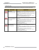
Receiver manual resets are needed in the following
situations:
• When operating in Trip Output mode, manual resets
are required only after a system lockout (see Section 5 for
causes).
• When the System is in Latch Output mode, a manual reset
is required at power-up, after each latch condition occurs, and
after a system lockout.
4.2.2 Emitter Resets
In the rare occurrence that an emitter requires a reset, power
the sensor down, then power it up. Emitter resets are needed
only if a lockout occurs.
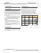
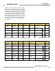
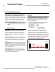
Figure 4-2. Emitter status indicators and operation
*See Section 5.1 for a description of error codes
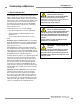
4.3 Status Indicators
A variety of status indicators on both the emitter and the receiver
are clearly visible on each sensor’s front panel (see Figure 4-1).
Emitter: A single bi-color red/green Status indicator shows
whether power is applied, and whether the emitter is in Run
mode, Test mode, or Lockout mode. A 7-segment diagnostic
display indicates a specific error code when the emitter is
in Lockout mode. The 7-segment display also momentarily
indicates the scan code setting at power-up or when changed.