
Safety Light Curtain Systems Owner's manual


38 P/N 68413 rev. A
Banner Engineering Corp. • Minneapolis, U.S.A.
www.bannerengineering.com • Tel: 763.544.3164
EZ-SCREEN Point
Instruction Manual
Operating Instructions
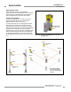
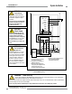
4.1 System Configuration Settings
System configuration settings are made on the configuration
panels located on each sensor, behind the threaded access
port cap (use the supplied spanner wrench to remove the cap).
See Figure 4.1. After configuration settings are verified/set, the
access port cap must be fully re-installed to maintain NEMA/IP
ratings. Other than scan code, all configuration settings
should be changed only when the system is off.
NOTE: The corresponding pairs of DIP switches must be
set identically for the System to operate.
Scan Code. Scan code is used to allow operation of multiple
pairs of emitters and receivers in close proximity (see Section
3.3.8). Scan code may be set to 1 or 2, using the switch on the
configuration panel. The scan code setting for each emitter
must agree with its corresponding receiver. The scan code
settings may be changed while in Run mode without causing a
lockout.
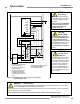
Figure 4-1. EZ-SCREEN Point configuration switches
BEAMS
1
2
R
E
S
E
T
S
T
A
T
U
S
EZ-SCREEN Point
BANNER ENGINEERING CORP., USA
888.373.6767
STATUS
SCAN
CODE
2
1
E
D
M
E
D
M
2 T 1 T 1
1 L 2 L 2
SCAN
CODE
BEAM
R
E
S
E
T
S
T
A
T
U
S
EZ-SCREEN Point
BANNER ENGINEERING CORP., USA
888.373.6767
Emitter
Receiver
Trip or Latch Output mode is selected on two DIP switches in
the receiver configuration port; see Figure 4.1. Both switches
must be set to the same setting. If they have different settings,
an error code will be displayed.
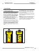
If the switches are set for Trip Output mode (T), the system will auto
reset. If the switches are set for Latch Output mode (L), the system
will require a manual reset.
EDM: EDM mode is selected via two DIP switches in the receiver
configuration port; see Figure 4-1. For 1-channel monitoring,
set both EDM DIP switches to the 1 position. For 2-channel
monitoring or no monitoring, set both EDM DIP switches to the 2
position. See Section 3.7.3 for more information.
4. System Operation