
Safety Light Curtain Systems Owner's manual


2 P/N 68413 rev. A
Banner Engineering Corp. • Minneapolis, U.S.A.
www.bannerengineering.com • Tel: 763.544.3164
EZ-SCREEN Point
Instruction Manual
Overview
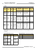
When multiple systems are used together in a grid, the beam
configuration (number of beams and beam spacing) required
for an application is determined by the application and the
safety standards being followed. U.S. applications are based on
recommendations in ANSI/RIA R15.06 and ANSI B11. European
applications are based on recommendations in EN 999. See
pages 63 and 64 for a list of applicable safety standards.
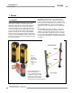
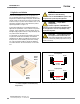
The ACCESS-GUARD configuration is used to guard the
entrance to an area, such as a robotic cell. Both the emitter and
receiver are mounted to one stand, so all wiring is located at
one side of the access point. Two mirrors, bracketed to face the
emitter and receiver at 45° angles, are installed at the opposite
side of the access point. The beam from the emitter crosses the
access point to the mirror opposite, reflects to the other mirror,
and back to the receiver. In this way, one beam is used to
simulate a two-beam sensing system (see Figure 1-1).
The emitter/receiver beams feature a narrow effective aperture
angle (EAA) for effective long-range sensing — up to 70
meters, depending on model. The EAA satisfies IEC 61496-2
(type 4), including requirements for extraneous reflections and
misalignment.
Cabling is accomplished in one of two ways. User-supplied
cable may be hard-wired into the emitter and receiver housings,
using the removable terminals in the end cap of each sensor,
or Mini-style quick-disconnect models are available for easier
installation; see pages 59-60. See Section 2.5 for cable
specifications and Section 3.7 for wiring instructions.
Banner EZ-SCREEN Point components may be purchased
individually, in sensor pair kits or in ACCESS-GUARD kits.
Sensor pair kits include one emitter, one receiver, a keyed Reset
switch, two cable glands, standard mounting hardware for both
sensors, plus the accessory spanner wrench. When purchased
separately, the emitter and receiver each include one cable
gland, mounting hardware for one sensor, plus the accessory
spanner wrench. The Keyed Reset switch also is available
separately, or other means may be used to reset the system
(see specifications in Section 2.5 for switch requirements). The
ACCESS-GUARD kit includes a short-range sensor pair, two
mirrors with 45° mounting brackets, and two 42” vertical stands
(see Figure 1-1).
The OSSD (solid-state safety outputs) are capable of performing
a “handshake” communication with the Muteable Safety Stop
Interface (MSSI) or Universal Safety Stop Interface (USSI) that
are found on other Banner Engineering safety products. The
handshake protocol is satisfied by any Banner Engineering
Safety Category 4 (per ISO 13849-1/EN954-1) device with OSSD
outputs or MSSI/USSI inputs.
To ensure a Safety Category 4 (per ISO 13849-1/EN954-1)
interface between the two devices, the MSSI/USSI provides a
“handshake request” that Banner Engineering safety devices
with OSSD solid-state outputs are capable of responding to. This
handshake verifies that the interface between the two devices is
capable of detecting certain unsafe failures that may occur, such
as a short-circuit to a secondary source of power or to the other
channel, high input resistance or loss of signal ground.