
Safety Light Curtain Systems Owner's manual


34 P/N 68413 rev. A
Banner Engineering Corp. • Minneapolis, U.S.A.
www.bannerengineering.com • Tel: 763.544.3164
EZ-SCREEN Point
Instruction Manual
System Installation
3.7.3 Machine Primary Control Elements and EDM Inputs
Each of the two Machine Primary Control Elements (MPCE1
and MPCE2) must be capable of immediately stopping the
dangerous machine motion, irrespective of the state of the
other. These two channels of machine control need not be
identical, but the stop time performance of the machine (Ts,
used to calculate the separation distance, see Section 3.3.1)
must take into account the slower of the two channels. Some
machines offer only one Primary Control Element. For such
machines, it is necessary to duplicate the circuit of the single
MPCE to add a second. Refer to Figures 3-19 and 3-20 or
consult the machine manufacturer for additional information.
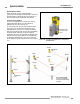
External Device Monitoring: It is strongly recommended
that one normally closed, forced-guided monitoring contact
of each MPCE be connected to EDM inputs (see Figures 3-
19 and 3-20). If this is done, proper operation of the MPCEs
will be verified. MPCE monitoring contacts is one method of
maintaining control reliability.
External Device Monitoring Hookup
Terminals 6 and 7 of the receiver terminal block provide
connection for the external device monitoring input. External
Device Monitoring (EDM) must be wired in one of three
configurations and must agree with the DIP switch EDM settings
on the receiver (see Section 4.1). One- and 2-channel EDM is
used when the EZ-SCREEN Point OSSD outputs directly control
the energizing and de-energizing of the guarded machine’s
MPCEs.
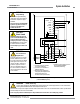
• One-channel monitoring is a series connection of closed
monitor contacts that are forced-guided (captive contact)
from each device controlled by the EZ-SCREEN System. The
monitoring contacts should open within 200 milliseconds of
the OSSD outputs turning on (a clear condition) and should
close within 200 milliseconds of the OSSD outputs turning off
(a blocked condition) or a lockout will occur (see Diagnostics,
Section 5.1). Refer to Figure 3-21 for 1-channel EDM hookup.
Connect the monitor contacts between +24V dc and EDM1
(terminal 6). Leave EDM2 (terminal 7) open (no connection).
Set the configuration DIP switches to 1, per Section 4.1.
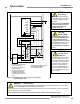
• Two-channel monitoring is a separate connection of closed
monitor contacts that are forced-guided (captive contact)
from each device controlled by the EZ-SCREEN Point. The
monitoring contacts should always change state (both open
or both closed) within 200 milliseconds of the corresponding
OSSD state change (turning on or off) or a lockout will occur
(see Diagnostics, Section 5.1). Refer to Figures 3-19 or 3-20
for 2-channel EDM hookup. Connect the monitor contacts as
shown between +24V dc and EDM1 (terminal 6) and between
+24V dc and EDM2 (terminal 7). Set the configuration
DIP switches to 2, per Section 4.1.
CAUTION . . .
EDM Monitoring
If configured for “No Monitoring,” it is the user’s
responsibility to ensure that this does not create a
hazardous situation.
NOTE: MPCE Monitoring
and Control Reliability
In the U.S., Control Reliability requires that a single failure
does not prevent a normal stop from occurring, or issues an
immediate stop command, and the next cycle is prevented
from occurring until the fault is corrected.
A common method of satisfying these requirements is the
use of 2-channel control with monitoring, where a normally
closed, forced-guided contact of each MPCE is wired as
described in the section at right and as shown in Figures
3-19, 3-20 and 3-21.
• No monitoring. Use this setting initially, in order to perform
the initial checkout; see Section 3.6. If No Monitoring is
selected, the user must ensure that any single failure of the
external devices does not result in a hazardous condition and,
in such a case, a successive machine cycle will be prevented
(see Section 1.3, Control Reliability). To configure the system
for no monitoring, set the configuration DIP switches to 2, per
Section 4.1, and connect a jumper (supplied) between EDM1
(terminal 6) and EDM2 (terminal 7).
3.7.4 Remote Test Input
A pair of terminals is provided on the emitter terminal block
(labeled TEST1 and TEST2) for the connection of an external
remote test switch (typically a normally open contact held
closed). This remote test input may be useful for EZ-SCREEN
System setup and checkout procedures. Opening this switch
“turns OFF” the emitter, simulating an interruption of the light
beam; all OSSD outputs will turn OFF. The device used must
be as specified in Section 2.5. (TEST1 and TEST2 terminals are
factory jumpered.)-
3.8 Preparing for System Operation
Perform the Commissioning Checkout, as described in Section
6.3.