
Safety Light Curtain Systems Owner's manual


P/N 68413 rev. A 33
Banner Engineering Corp. • Minneapolis, U.S.A.
www.bannerengineering.com • Tel: 763.544.3164
EZ-SCREEN Point
Instruction Manual
System Installation
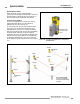
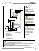
2-Channel (Dual-Channel) Control
Two-channel control provides the ability to electrically extend
the safe switching point beyond the FSD contacts. With proper
monitoring (i.e. EDM), this method of interfacing is capable
of detecting certain failures in the control wiring between the
safety stop circuit and the MPCEs. These failures include a
short-circuit of one channel to a secondary source of energy or
voltage, or the loss of the switching ability of one of the FSD
outputs. Such failures could lead to the loss of redundancy — or
to a complete loss of safety, if not detected and corrected.
The possibility of a failure to the wiring increases as the physical
distance between the FSD safety stop circuits and the MPCEs
increase, as the length or the routing of the interconnecting
wires increases, or if the FSD safety stop circuits and the
MPCEs are located in different enclosures. For this reason,
2-channel control with EDM monitoring should be used in any
installation where the FSDs are located remotely from the
MPCEs.
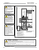
1-Channel (Single-Channel) Control
One-channel control, as mentioned, uses a series connection of
FSD contacts to form a safe switching point. After this point in
the machine’s safety-related control system, failures can occur
that would result in the loss of the safety function (such as a
short-circuit to a secondary source of energy or voltage).
For this reason, 1-channel control interfacing should be used
only in installations where FSD safety stop circuits and the
MPCEs are mounted within the same control panel, adjacent to
each other, and are directly connected to each other; or where
the possibility of such a failure can be excluded. If this can not
be achieved, then 2-channel control should be used.
Methods to exclude the possibility of these failures include, but
are not limited to:
• Physically separating interconnecting control wires from each
other and from secondary sources of power.
• Routing interconnecting control wires in separate conduit,
runs, or channels.
• Locating all elements (modules, switches, and devices under
control) within one control panel, adjacent to each other, and
directly connected with short wires.
• Properly installing multi-conductor cabling and multiple wires
through strain-relief fittings. (Over-tightening of a strain-relief
can cause short-circuits at that point.)
• Using positive-opening or direct-drive components, installed
and mounted in a positive mode.