
Safety Light Curtain Systems Owner's manual


32 P/N 68413 rev. A
Banner Engineering Corp. • Minneapolis, U.S.A.
www.bannerengineering.com • Tel: 763.544.3164
EZ-SCREEN Point
Instruction Manual
System Installation
3.7 Electrical Interface to the Guarded Machine
(Permanent Hookup)
Make the electrical connections as described in Sections 3.7.1
to 3.7.4 as required by each individual application.
Supply power and the external Reset switch should be
previously connected by this point. The EZ-SCREEN must
also have been aligned and passed the Initial Checkout, as
described in Section 3.6. The final connections to be made are:
• OSSD outputs
•FSD interfacing
• MPCE/EDM connections
• Remote Test
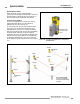
3.7.1 OSSD Output Connections
Both the Output Signal Switching Device (OSSD) outputs must
be connected to the machine control so that the machine’s
safety-related control system interrupts the circuit or power to
the Machine Primary Control Element(s) (MPCE), resulting in a
non-hazardous condition.
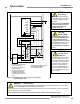
Final Switching Devices (FSDs) typically accomplish this when
the OSSDs go to an OFF state. See Figure 3-19.
3.7.2 FSD Interfacing Connections
FSDs (Final Switching Devices) can take many forms, though
the most common are captive contact, forced-guided relays
or interface modules. The mechanical linkage between the
contacts allows the device to be monitored by the External
Device Monitoring circuit for certain failures.
Depending on the application, the use of FSDs can facilitate
controlling voltage and current that differs from the OSSD
outputs of the EZ-SCREEN. FSDs can also be used to control
an additional number of hazards by creating multiple safety stop
circuits.
Safety Stop Circuits
A safety stop allows for an orderly cessation of motion for
safeguarding purposes, which results in a stop of motion and
removal of power from the MPCEs (assuming this does not
create additional hazards). A Safety Stop Circuit typically
comprises a minimum of two normally open (N.O.) contacts
from captive contact, forced-guided relays, which are monitored
(through External Device Monitoring) to detect certain failures
in order to prevent the loss of the safety function. Such a circuit
can be described as a “safe switching point.”
WARNING . . .
Interfacing of both
OSSDs
Both of the OSSD (Output Signal Switching
Device) outputs must be connected to the machine control
so that the machine’s safety-related control system interrupts the
circuit to the machine primary control element(s), resulting in a non-
hazardous condition.
Never wire an intermediate device(s) in such a manner that the
safety function can be suspended, overridden, or defeated,
unless accomplished in a manner at the same or greater
degree of safety.
WARNING . . .
OSSD Interfacing
To ensure proper operation, the EZ-SCREEN
OSSD output parameters and machine input
parameters must be considered when interfacing the EZ-SCREEN
solid-state OSSD outputs to machine inputs.
Machine Control circuitry must be designed so that the maximum
load resistance value is not exceeded and that the maximum
specified OSSD OFF-state voltage does not result in an
ON condition.
Failure to properly interface the OSSD outputs to the guarded
machine could result in serious bodily injury or death.
Typically, safety stop circuits are either 1-channel (single
channel), which is a series connection of at least two N.O.
contacts; or 2-channel (dual channel), which is a separate
connection of two N.O. contacts. In either method, the safety
function relies on the use of redundant contacts to control a
single hazard (if one contact fails ON, the second contact will
arrest the hazard and prevent the next cycle from occurring).
The interfacing of the Safety Stop Circuits must be accomplished
so that the safety function can not be suspended, overridden,
or defeated, unless accomplished in a manner at the same or
greater degree of safety as the machine’s safety related control
system that includes the EZ-SCREEN.
The normally open safety outputs from an interface module
provide a series connection of redundant contacts that form
safety stop circuits for use in either 1-channel or 2-channel
control. (See Figure 3-19.)