
Safety Light Curtain Systems Owner's manual


P/N 68413 rev. A 31
Banner Engineering Corp. • Minneapolis, U.S.A.
www.bannerengineering.com • Tel: 763.544.3164
EZ-SCREEN Point
Instruction Manual
System Installation
WARNING . . .
If Trip Test Indicates a
Problem
If the EZ-SCREEN System does not respond
properly to the Trip Test, do not attempt to use the System. If
this occurs, the System cannot be relied upon to stop dangerous
machine motion when a person or object enters the light grid.
Serious bodily injury or death could result.
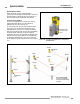
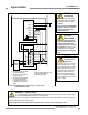
1. Attach the battery-powered LAT-1 to the housing of the
emitter over the beam location, using the EZ-SCREEN
bracket clip included with the tool. A dot on the sensor
housing next to the lens window indicates the beam’s
location. Align the hole on the LAT-1 over the beam marking
(see Figure 3-15).
NOTE: To find the general direction the laser beam is pointing,
place a target at arm’s reach, look alongside the LAT-1,
and slowly raise the target until the red dot appears on
it. Using this method and rotating the emitter will send
the beam in the approximate direction of the receiver. If
the dot still cannot be located at the receiver (or mirror),
“walk” the target down the path of the beam, while
keeping the dot centered on the target, until the desired
range is reached.
2. If no corner mirrors are used in the application, attach or
hold a piece of reflective material, such as white paper, the
reflective tape included with the LAT-1, or the optional clip-
on reflective target, to the receiver at the beam location.
Do not affix the self-adhesive backing of the reflective
material to the sensor windows or to the mirror surfaces;
the adhesive residue may not be easy to remove. See
Figure 3-16.
If corner mirrors are used, or if installing the ACCESS-
GUARD kit, attach or hold the reflective material at the beam
height in the approximate center of mirror #1.
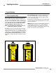
3. The Laser Alignment Tool emits a bright red pinpoint of
light along the same path as the emitter beam. Adjust the
emitter tilt and rotation until the LAT-1 beam is centered over
the receiver (or mirror) beam location. Partially tighten the
emitter mounting hardware to prevent misalignment when the
LAT-1 is later removed. (If no mirrors are used, proceed to
step 5. If mirrors are used, proceed to step 4.)
4. After the emitter beam is aligned on the first mirror, remove
the reflective material from that mirror and repeat the
process on the second mirror. Repeat the process for each
mirror in succession, until the laser beam shines on the
reflective material positioned at the receiver beam location.
5 Position the LAT-1 on the receiver housing, centered over the
beam location. Align the receiver beam as described in step
3 for the emitter. (Mirrors, if used, normally should not require
realignment.) Partially tighten the receiver mounting hardware
to prevent misalignment when the LAT-1 is removed, and
remove the LAT-1.
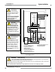
Figure 3-17. Using the optional clip-on retroreflector for
alignment
When the emitter is properly aligned, the laser beam hits the screw
in the center of the reflector and the “glow” will dim slightly.
Emitter
Receiver
Using the System for Alignment
Power-up the EZ-SCREEN Point system and use the Beam
Status indicator on the receiver to align the system by rotating
the emitter and receiver sensors. Do not adjust the tilt of
either sensor unless absolutely necessary to align or optimize
alignment. System alignment is optimized when the Beam Status
indicator is steady Green.
When alignment is optimized, tighten the mounting screws and
the mounting stand base nuts, or other mounting hardware, to
secure the emitter, the receiver, and any mirrors used.
Perform the trip test (described in Section 6.2) to verify proper
system operation and to detect possible reflection problems.
Do not continue operation until the entire checkout
procedure is completed and all problems are corrected.