
Safety Light Curtain Systems Owner's manual


P/N 68413 rev. A 29
Banner Engineering Corp. • Minneapolis, U.S.A.
www.bannerengineering.com • Tel: 763.544.3164
EZ-SCREEN Point
Instruction Manual
System Installation
Temporary Power
1. Inspect the area near the light beam (including work pieces
and the guarded machine) for reflective surfaces. (Reflective
surfaces may cause light to reflect around a person in
the beam, preventing the person from being detected and
not stopping the machine motion.) Remove the reflective
surfaces as possible by relocating them, painting, masking or
roughening them. Remaining problem reflections will become
apparent during step 5.
2. Verify that power is removed from the EZ-SCREEN System
and from the guarded machine. Remove all obstructions from
the light beam. Leaving power to the guarded machine OFF,
power up the EZ-SCREEN System. Verify that input power is
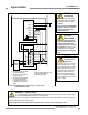
present to both emitter and receiver. Do not operate the EZ-
SCREEN System without a proper earth ground at the
terminal on both sensors, as shown in Figures 3-18
through 3-21. At least one indicator on both emitter and
receiver should be ON.
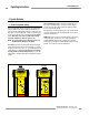
3. Observe the Beam Status indicator on the receiver to
determine light grid alignment status:
A blocked condition is indicated by the Status indicator
steady Red, and the Beam Status indicator steady Red.
A clear condition is indicated by the Beam Status indicator
steady Green. (It will flicker Green if excess gain is
marginal.)
A latch condition is indicated by the receiver Status
indicator steady Red. The Beam Status indicator may
be Red, Green, or flashing Green, depending on beam
status. In Latch Output mode, the outputs come back on only
when the beam is clear and after a manual reset.
A lockout condition is indicated by the receiver Status
indicator single-flashing Red, and the receiver Reset
indicator OFF.
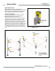
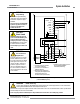
Reset Switch Hookup
Connect the external Reset switch to the Reset terminal on the
receiver terminal block and to 24V dc (see Figures 3-19, 3-20
and 3-21).
Configuring the System for Initial Checkout
Verify that the System is set to the factory presets for initial
checkout and optical alignment. (Factory presets are for Latch
Output, 2-Channel EDM, and Scan Code 1; receiver terminals 6
and 7 should be connected, as described in step 4 above.) See
Figure 4-1.
3.6 Initial Checkout and Optical Alignment Procedure
Verifying System Operation
The initial checkout procedure must be performed by a Qualified
Person (see WARNING, page 17). It must be performed only
after configuring the System and after connecting the emitter and
receiver per Section 3.5.
The procedure is performed on two occasions:
• To ensure proper installation when the System is first installed,
and
• To ensure proper System function whenever any maintenance
or modification is performed on the System or on the
machinery being guarded by the System. (See Section 6.1 for
a schedule of required checkouts.)
For the initial checkout, the EZ-SCREEN Point System must be
checked without power being available to the guarded machine.
Final interface connections to the guarded machine cannot
take place until the Point system has been checked out.
Verify that:
• Power has been removed from (or is not available to) the
guarded machine, its controls or actuators; and
• The machine control circuit is not connected to the OSSD
outputs at this time (permanent connections will be made
following this initial checkout); and
• EDM has been configured for No Monitoring, per Section 3.5.