
Safety Light Curtain Systems Owner's manual


28 P/N 68413 rev. A
Banner Engineering Corp. • Minneapolis, U.S.A.
www.bannerengineering.com • Tel: 763.544.3164
EZ-SCREEN Point
Instruction Manual
System Installation
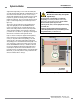
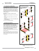
For easy wiring, each EZ-SCREEN sensor has a removable
modular terminal block inside one end cap, at the same end as
the indicators (See Figure 3-14). To make connections:
1. Remove the wiring chamber end cap by unscrewing the four
captive screws in the end cap corners.
2. Remove the terminal block from the end cap.
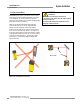
3. Remove one or more of the three Pg13.5 plugs, as needed,
from their threaded access ports, using the accessory
spanner wrench. Insert conduit or a cable gland into the
port; screw snugly into place. Follow the specific installation
instructions and/or recommendations supplied by the
hardware manufacturer. Unused access ports should remain
factory sealed to maintain NEMA 4, 13; IEC IP65 rating.
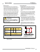
4. Route the wires or cabling through the bracket (if necessary)
and the wiring chamber end cap. Remove outer cable
insulation as necessary (approximately 1" to 2") and strip the
individual wire insulation approximately 7 mm (0.25"); make
connections to terminals as indicated in Figure 3-14. Torque
the terminal screws to 0.22 to 0.25 N m (1.9 to 2.2 in. lb.)
recommended torque.
Emitter: If Test input will be used, connect the wires at the
emitter terminal block and temporarily connect the other ends
of the wires to each other (but not to an external contact at
this time).
If Test input will not be used, leave the factory jumper in
place.
Terminals 7, 8 and 9 are provided to allow convenient power
connection (24V dc, 2 amp max.) to another EZ-SCREEN
emitter. These terminals are a direct connection to terminals
3, 2 and 1 respectively. A 24V dc, 2-amp external fuse is
recommended to limit the current on terminal 7.
Receiver: While all wires will not be connected to the machine
control circuits at this time, connect the receiver end of all wires
to their connections on the receiver terminal block.
If EDM will not be used (no monitoring), jumper terminals 6 and
7. (A jumper wire is supplied in the hardware kit.)
If 2-channel monitoring will be used, connect the wires to
receiver terminals 6 and 7 and temporarily connect the other
ends of the wires to each other (but not to the machine at this
time).
If 1-channel monitoring will be used, add a jumper between
terminals 6 and 7 for the initial checkout. Final EDM wiring must
be completed later.
5. Recheck the wires to be sure connections are accurate and
that wiring complies with applicable (international, national
and local) codes.
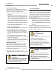
6. Snap the terminal block back into the end cap. Replace the
end cap on the end of the housing, being careful to align the
end cap terminals with the corresponding terminals in the
housing. When the end cap is screwed back into place on
the housing, the two terminal block sections will automatically
connect.
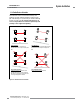
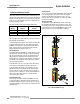
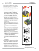
Figure 3-14 Making connections
to the sensor terminal
blocks
Emitter
Terminal
Block
PE
1
9
dc COM
+24V dc
TEST2
TEST1
(Not Used)
+24V dc
dc COM
PE
Receiver
Terminal
Block
PE
1
9
dc COM
+24V dc
(Not Used)
RESET
EDM1
EDM2
OSSD1
OSSD2