
Safety Light Curtain Systems Owner's manual


26 P/N 68413 rev. A
Banner Engineering Corp. • Minneapolis, U.S.A.
www.bannerengineering.com • Tel: 763.544.3164
EZ-SCREEN Point
Instruction Manual
System Installation
Mounting the Sensors
All system components (emitter, receiver, and corner mirrors, if
used), must be parallel to each other and perpendicular to the floor.
If the floor is level, the components may be checked for plumb,
using a level, for example. If the floor is sloped, alignment is more
complex, because the floor-to-bottom-beam measurement must
remain constant, or not exceed the maximum height above the floor.
If the floor has a dip, as for a drain, or is raised up within the path of
the beams, corrective measures must be taken to ensure that the
requirements of ANSI/RIA R15.06, ANSI B11 or EN999 are met
(see Figure 3-13). It is important that the distances between the
top and bottom beams and the floor meet the requirements of the
applicable standards, throughout the length of the beam path.
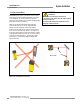
Installation Without Mirrors
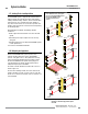
1. If using Banner MSA series stands and bases to mount the EZ-
SCREEN emitter and receiver, position the bases at the desired
locations and loosely mount using the bolt locations in the four
corners as described in the MSA literature. Do not tighten the
mounting nuts, because the stand and sensor must still be
leveled.
Other stands and bases may be used to mount the EZ-SCREEN
system, but must allow the sensors to tilt (both front-to-back and
side-to-side) to accommodate sloping floor surfaces and the
alignment procedure. When fixed stands and bases are used,
the EZA-MBK-9 brackets may be used to provide the necessary
adjustability for alignment.
2. Mount the emitters and the receivers, using the supplied EZ-
SCREEN mounting brackets, so that the beam closest to the
floor is at the proper height, typically 12" or 16" (see Figure 3-13)
from the floor. Refer to the appropriate standards for specifics
on the correct beam configuration and mounting of EZ-SCREEN
Point systems. Do not fully tighten the screws until the sensors
are aligned.
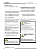
3. Position the emitter and receiver housings so that they are
perpendicular to the floor in all dimensions, with their windows
facing each other. If the floor is level, use a level to check for
plumb.
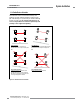
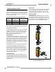
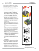
Figure 3-13. Verify required height between the top and bottom beams and the floor, throughout the length of the beam path, per
applicable standards.
Emitter
Mirror #1
Mirror #2
Receiver
H2
H3
H1
Level
H1 is the distance between the top beam and the floor.
H2 is the distance between the bottom beam and the floor.
H3 is the beam spacing.
Floor
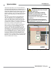
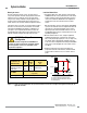
WARNING . . . Proper Beam
Configuration
The beam configuration of EZ-SCREEN Point
Systems must meet the requirements of applicable standards
for each application. It is the user’s responsibility to verify
proper beam configuration.
per ANSI B11 and
ANSI/RIA R15.06
Top
Beam
H1
Bottom
Beam
H2
Distance Between
Beams*
H3
2-Beam Reach-Over
Applications (bending
at the waist)
0.9 m
(36")
0.3 m
(12")
584 mm (23")
per EN999
Beam Heights Above Reference Plane
(e.g., Floor)
2-Beam Applications 0.4 m, 0.9 m (16", 36")