
Safety Light Curtain Systems Owner's manual


P/N 68413 rev. A 25
Banner Engineering Corp. • Minneapolis, U.S.A.
www.bannerengineering.com • Tel: 763.544.3164
EZ-SCREEN Point
Instruction Manual
System Installation
3.4 Mechanical Mounting Procedure
Short-range emitters and receivers may be mounted up to 20 m
(65') apart. Long-range emitters and receivers may be mounted
between 15 m (49') and 70 m (230') apart. If Banner SSM corner
mirrors are used, the total range decreases by approximately 8
percent per mirror, as follows:
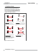
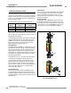
The emitter and the receiver must be mounted parallel to each
other; see Figure 3-8. If corner mirrors are used, they must also be
mounted in the same parallel line.
Several mounting bracket options are available; refer to Section
2.2 for more information. Brackets may attach directly to EZ-
SCREEN sensor end caps, or at any point along the sensor’s
length, using the supplied T-nuts in the housing’s side slots.
Bracket dimensions are shown in Figure 2-1.
Standard Brackets
The standard brackets (EZA-MBK-1), included with each sensor,
may attach to the side of the housing or to the top and bottom
end caps. If mounting to the end caps, the beam path may run
either parallel or perpendicular to the mounting surface. The
brackets allow ±30° rotation for beam alignment. Insert the two
included M5 screws through the slots in the brackets, into the
end cap’s two threaded holes.
If mounting to the end caps, see Section 3.5 for cable routing
instructions prior to attaching the housing to the bracket.
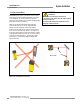
If side-mounting to the housing, lay the housing on its side
and slide two T-nuts into the slot on one side of the housing.
Connect a bracket near the center of the sensor, using two T-
nuts and screws; see Figure 3-12. For easier optical alignment,
swivel brackets (described below) are recommended when
sensors will be side-mounted.
Stand-Mount Brackets
The accessory stand-mount brackets (EZA-MBK-2) are used
in conjunction with the standard brackets described above for
mounting to an MSA Series stand. They may also be used with
a U-bolt for attaching to a round stand, such as Machine Guard
stand MGA-S72-1.
1
1
ON
2 3
4
SCAN
CODE
2
1
T
L
1
2
T
L
1
E
D
M
E
D
M
2
S
T
A
T
U
S
BEAM
R
E
S
E
T
S
T
A
T
U
S
EZ-SCREEN Point
BANNER ENGINEERING CORP., USA
888.373.6767
1
1
ON
2 3 4
SCAN
CODE
2
1
T
L
1
2
T
L
1
E
D
M
E
D
M
2
S
T
A
T
U
S
BEAM
R
E
S
E
T
S
T
A
T
U
S
EZ-SCREEN Grid
BANNER ENGINEERING CORP., USA
888.373.6767
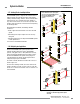
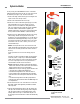
Figure 3-12. Attaching standard brackets to the end caps or
side of the EZ-SCREEN housing
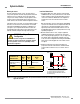
Swivel Brackets
The accessory swivel brackets (EZA-MBK-3) mount to the sides
of the housing using the same T-nuts used for the standard
brackets. The two-part brackets rotate up to 180° for easy
alignment. After sensors are aligned (see Section 3.6), tighten
brackets firmly into place.
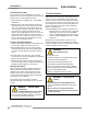
Adjustable Brackets
The adjustable brackets (EZA-MBK-9) mount to the housing
top and bottom and allow the space between the sensor and
its mounting surface to be increased or decreased. When fixed
stands and bases are used, the EZA-MBK-9 brackets may be
used to provide the necessary adjustability for alignment.
Corner
Mirrors*
Short-Range
Systems
Long-Range
Systems
1 18.3 m (60') total 64 m (210') total
2 16.8 m (55') total 59.5 m (195') total
3 15.2 m (50') total 55 m (180') total
*NOTE: These figures do not apply to ACCESS-GUARD configurations.