
Safety Light Curtain Systems Owner's manual


P/N 68413 rev. A 17
Banner Engineering Corp. • Minneapolis, U.S.A.
www.bannerengineering.com • Tel: 763.544.3164
EZ-SCREEN Point
Instruction Manual
System Installation
Sensing Mode Configurations
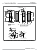
In opposed-mode configuration, the emitter and receiver are
mounted opposite from each other to form a single beam (see
Figure 3-3). Opposed-mode configuration can be combined with
vertical corner mirrors for perimeter-guarding applications, as
shown in Figure 3-4 and described in Section 3.3.6.
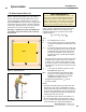
Access-Guard Configurations
In access-guard configuration, the emitter and receiver are
used with two angled mirrors to create multiple beams from one
EZ-SCREEN Point System – in effect, forming a vertical light
grid using one beam. The ACCESS-GUARD kit is available for
constructing this configuration (see Figure 3-3 and Section 2.1).
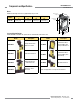
Figure 3-3. EZ-SCREEN Point sensing mode configurations
Two-Beam Opposed-Mode
configuration
Emitter
Receiver
Receiver
Emitter
Receiver
Emitter
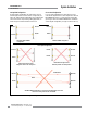
ACCESS-GUARD configuration set too far apart and misaligned can result in
voids in the sensing area. Path A is unintended.
ACCESS-GUARD configuration
Receiver
Emitter
Intended Path
Path A
Emitter
Emitter
Receiver
Emitter
Receiver
Mirror #2
Mirror #1
Single opposed mirror leaves
dangerous voids in the sensing area
Both emitters facing the same
direction provides crosstalk potential
Unacceptable Configurations
Receiver